Track having rotatable bushing and link for the same

a technology of rotatable bushings and track, which is applied in the direction of driving chains, hinges, transportation and packaging, etc., can solve the problems of machining work troublesome, rigidity falling considerably in comparison with conventional tracks without rotatable bushings, and affecting the smooth transmission of power, so as to prevent internal deformation. , the effect of smooth transmission

Active Publication Date: 2008-02-05
KOMATSU LTD
View PDF23 Cites 21 Cited by
  • Summary
  • Abstract
  • Description
  • Claims
  • Application Information

AI Technical Summary

Benefits of technology

[0010]In accordance with the present invention, a track link is composed of a combination of an internal link with an external link. With respect to the external link to which a coupler pin is attached, the thickness of a bushing hole portion of the internal link into which a bushing to be externally interfitted onto the coupler pin is incorporated is made greater than the thickness of a coupler pin hole portion of the external link. As a result of such arrangement, the strength on the bushing incorporated side is enhanced, and stress acting on both the internal and external links becomes balanced, and rigidity deficiency in the bushing side link (the internal link) is eliminated. It becomes possible to obtain a balanced track link and the strength of track is enhanced.
[0019]In accordance with the external link of the present invention, interference with the internal link at the connecting part is eliminated, thereby making it possible to secure a required interfit space for the interfitting of the coupler pin to the external link. The effect of smoothly transmitting power is obtained. Additionally, also during the link molding process, the occurrence of internal deformation is prevented as is in the internal link.

Problems solved by technology

Accordingly, in the conventional track 60, the track bushing 72 wears off soon, and the frequency of replacement of the track bushing 72 is high, thereby producing the problem that running costs become expensive.
In this construction assembled as a link assembly, a pair of link pieces and a coupler pin are merely rigidly joined, so that there occurs a high stress between the pin mount part and a track shoe mount part, thereby producing the problem that rigidity falls considerably in comparison with conventional tracks without rotatable bushings.
This not only makes machining work troublesome but also produces the problem that assembling work becomes complicated.
Furthermore, in the aforesaid (1979)4206 technique, there occurs insufficiency in strength on the coupler pin side of the link piece.

Method used


Image

  • Track having rotatable bushing and link for the same
  • Track having rotatable bushing and link for the same
  • Track having rotatable bushing and link for the same

Examples


Embodiment Construction

[0027]Hereinafter, referring to the drawings, a specific embodiment of a track with a rotatable bushing and a link for a track with a rotatable bushing according to the present invention will be described below.

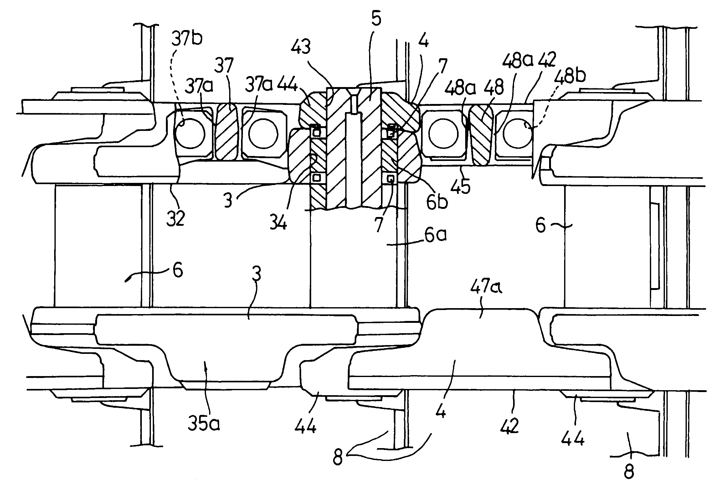
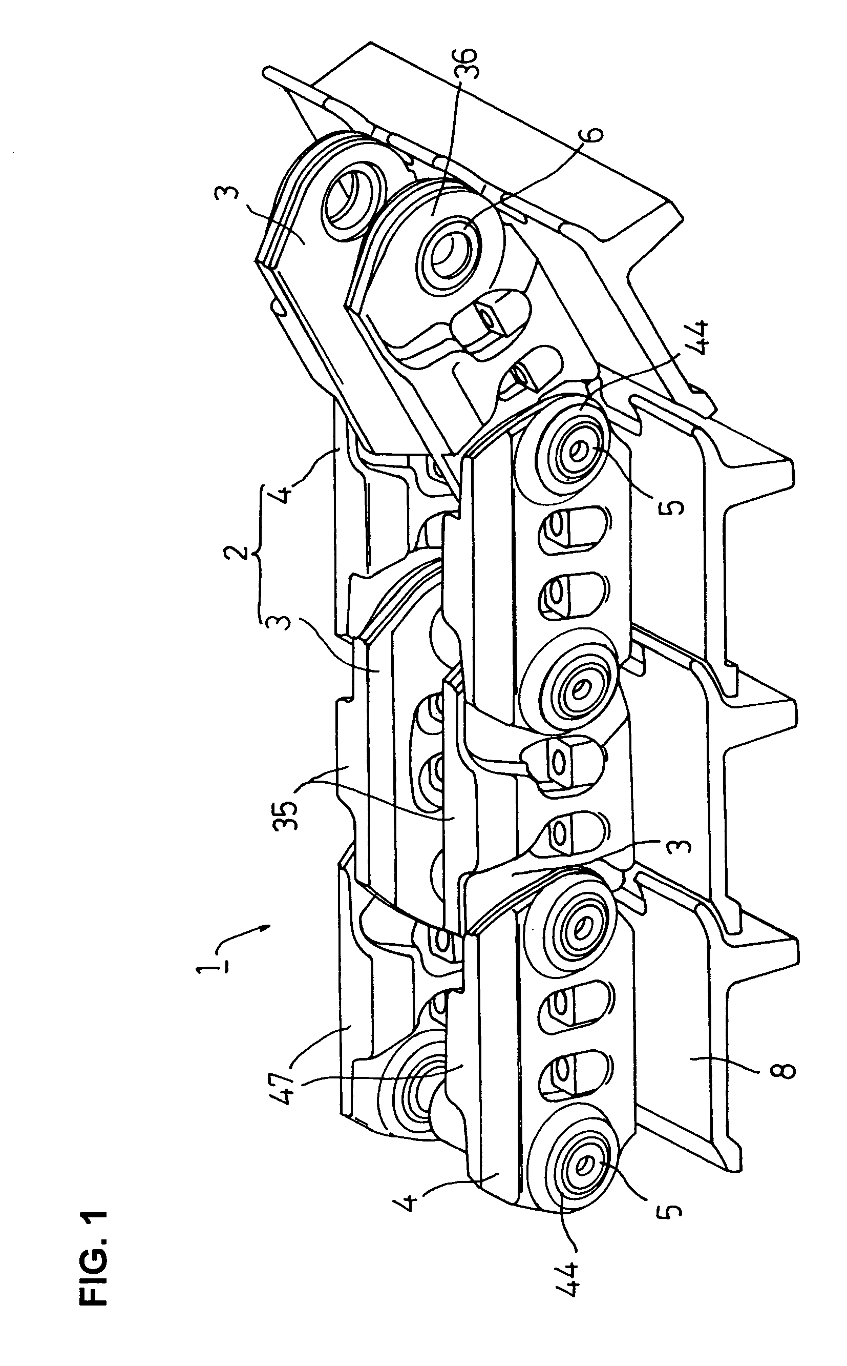
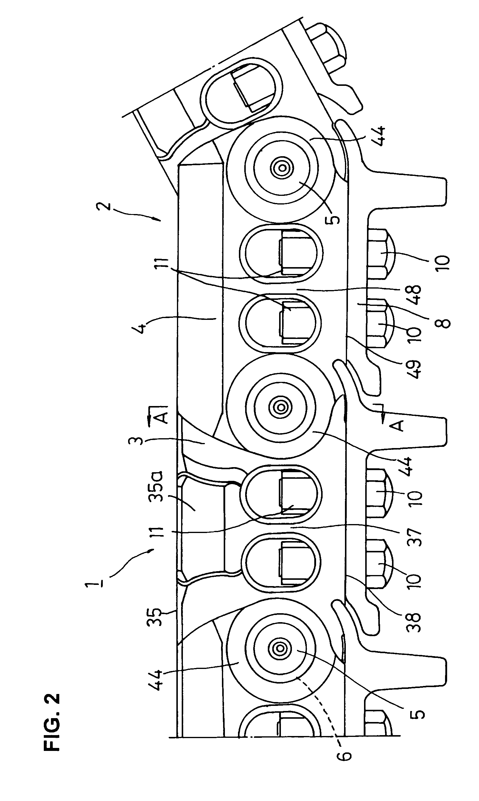
[0028]FIG. 1 is a partial perspective illustration of a track according to an embodiment of the present invention. FIG. 2 is a partial front view of the track. FIG. 3 is a top plan view showing, in cross section, a part of FIG. 2. FIG. 4 is an enlarged cross sectional view taken on the line A-A of FIG. 2. FIG. 5 is a perspective illustration of an internal link of the track. FIG. 6 is a perspective illustration of an external link of the track.

[0029]A track 1 with a rotatable bushing of the present embodiment is usually incorporated into an undercarriage (not shown) of a track-type construction machine (work machine) such as a hydraulic excavator, a bulldozer et cetera. As partially shown in FIG. 1, the track 1 with the rotatable bushing (hereinafter called the “track 1”) com...


PUM

PropertyMeasurementUnit
widthaaaaaaaaaa
circumferenceaaaaaaaaaa
thicknessaaaaaaaaaa

Abstract

In a track with a rotatable bushing which is brought into engagement with a sprocket of a track-type vehicle, it is intended that strength is enhanced rationally by link functionality sharing and by combination of such assigned functional tasks for achieving further improvements in rotatable bushing function. To this end, a track link comprises a combination of an external link and an internal link; a coupler pin hole is provided through the external link; a bushing hole is provided through the internal link, and the thickness dimension of a bushing hole formation part of the internal link is made greater than that of a coupler pin formation part of the external link.

Description

TECHNICAL FIELD[0001]The present invention relates to a track and its link for track-type work machines. More particularly, this invention is directed to a track with a rotatable bushing and to a link for such a track with a rotatable bushing for the achievement of improvement in the strength of a connection part comprising a combination of an internal link and an external link.BACKGROUND ART[0002]A track on a under carriage of a track-type work machine (such as a hydraulic excavator, bulldozer et cetera) conventionally comprises endlessly-coupled track links and track shoes mounted on the respective track links. The track is passed around a sprocket and idler which are supported on the vehicle frame and disposed at required intervals. Engaged with a sprocket, each track link is driven. The track is supported by track rollers and carrier rollers disposed between the sprocket and idler in the vehicle frame. The track-type work machine travels by such arrangement.[0003]Referring to FI...

Claims


Application Information

Patent Timeline
Patent Type & Authority Patents(United States)
IPC IPC(8): B62D55/21B62D55/18
CPCB62D55/21B62D55/104B60Y2304/07B60Y2304/05
Inventor YAMAMOTO, TEIJIMAEDA, KAZUO
Owner KOMATSU LTD
Why Eureka
Try Eureka