Anesthesia manifold and induction valve

a technology of induction valve and manifold, which is applied in the direction of valves, intravenous devices, etc., can solve the problems of inconvenient manipulation, inconvenient manipulation, and inability to adjust the position of the manifold, so as to improve the induction valve mechanism.

Active Publication Date: 2008-02-05
ELCAM PLASTICS
View PDF57 Cites 65 Cited by
  • Summary
  • Abstract
  • Description
  • Claims
  • Application Information

AI Technical Summary

Benefits of technology

[0007]The present invention is directed to an improved anesthesia manifold and an improved induction valve mechanism. A plurality of induction valve elements may be joined or “ganged” together in order to define a manifold. In the preferred embodiment of the induction manifold, at least two individual valve elements are combined to form the manifold. Each of the plurality of valve elements includes the following components: (1) a valve body; (2) a first inlet port carried by the valve body and defining at least in part a central fluid communication flow path for supplying intravenous fluid to patient; and (3) a second inlet port carried by the valve...

Problems solved by technology

While such devices function well, they require many handle manipulations.
Such manipulations are not only tedious but they also can lead to errors.
For instance, manipulating the handles of a stopcock manifold in the wrong way can result in t...

Method used


Image

  • Anesthesia manifold and induction valve
  • Anesthesia manifold and induction valve
  • Anesthesia manifold and induction valve

Examples


Embodiment Construction

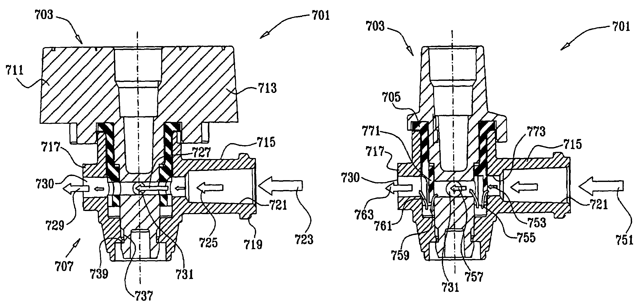
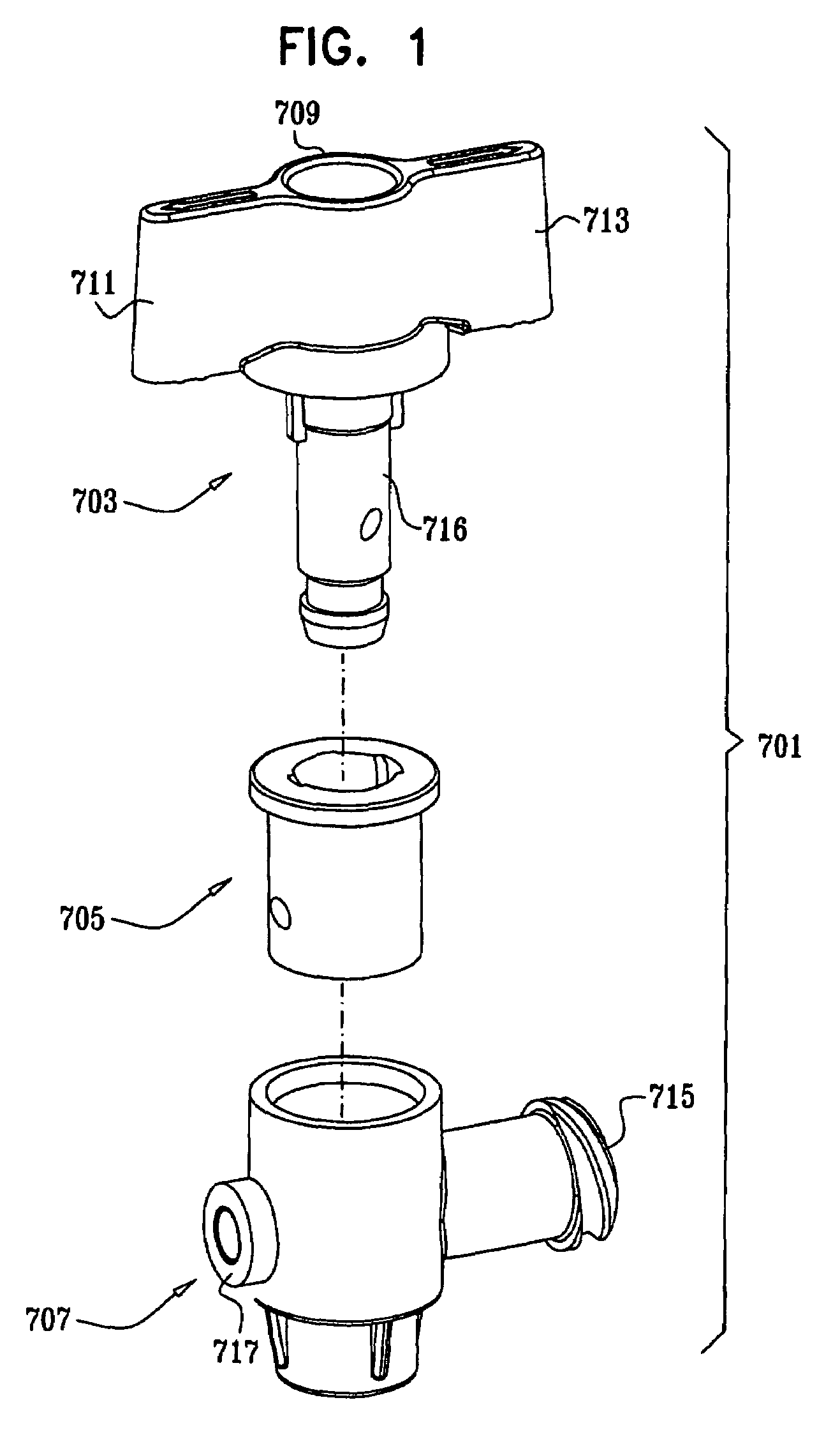
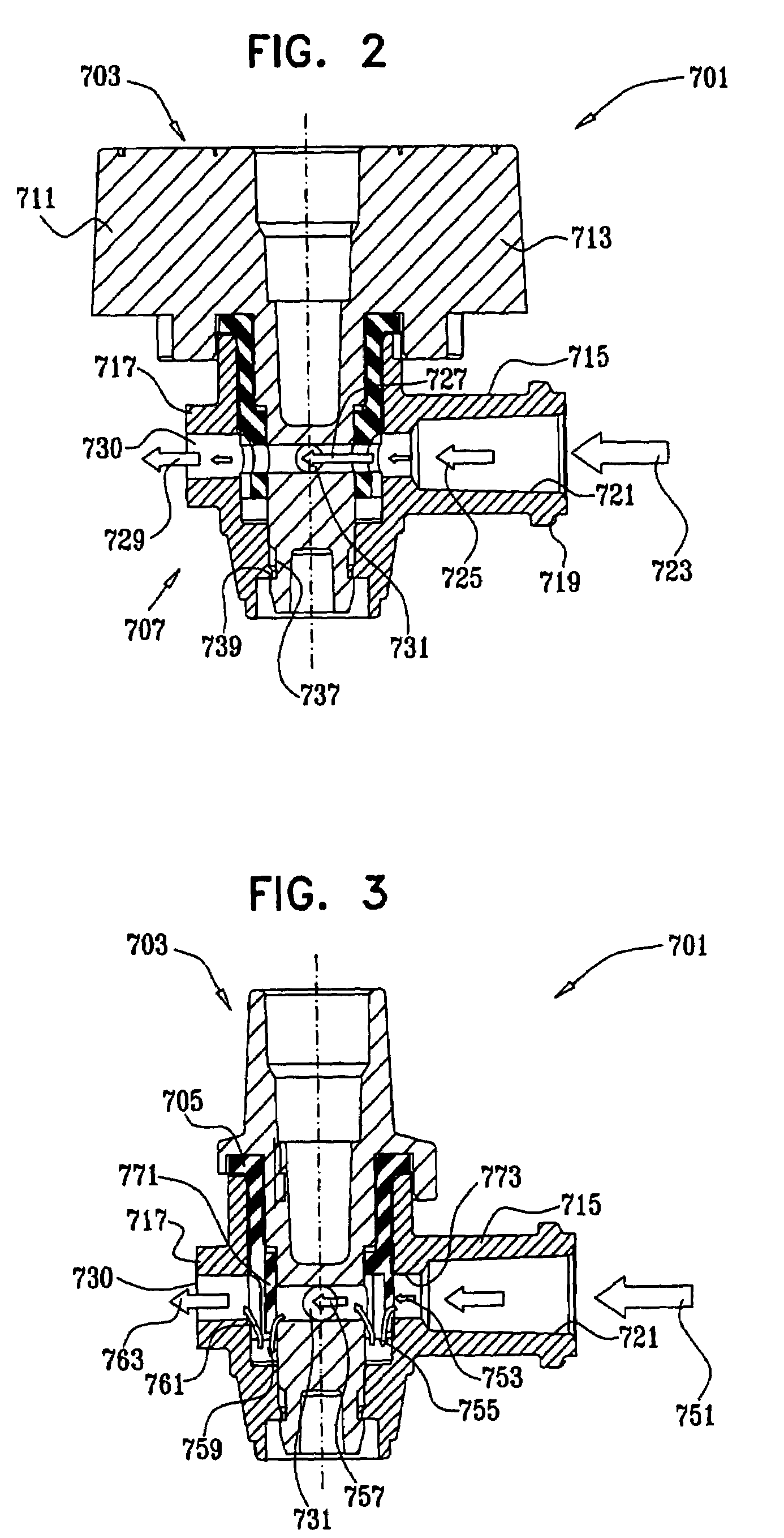
[0016]The present invention is directed to an improved valve manifold for use in delivering liquid anesthesia. The invention includes novel valve elements which can be “ganged” together to constitute a manifold. The embodiment described in this application has several operational attributes, including: (1) the manifold is made up of a plurality of independently-operable valve elements; (2) each valve can be individually controlled and moved between any one of a plurality of predefined operating modes; and (3) the two basic modes of operation include a pressure-activated flow mode of operation, and an aspiration / backflow / purge / sample mode of operation.

[0017]In operation, anesthesia drugs are administered through each individual valve of the valve manifold. The valve allows the anesthesia drug to mix into an IV line which receives a saline drip from an IV bag and delivers the mixture of saline fluid and the anesthesia drug to the patient intravenously through an IV catheter.

[0018]In t...


PUM


Abstract

The present invention is directed to an improved anesthesia manifold and an improved induction valve mechanism. A plurality of induction valve elements may be joined or “ganged” together in order to define a manifold. In the preferred embodiment of the induction manifold, at least two individual valve elements are combined to form the manifold. Each of the plurality of valve elements includes the following components: (1) a valve body; (2) a first inlet port carried by the valve body and defining at least in part a central fluid communication flow path for supplying intravenous fluid to patient; and (3) a second inlet port carried said valve body and at least in part defining an anesthesia drug inlet. Each of the plurality of valve components: (1) an induction valve mechanism which maintains said second inlet port in a closed condition until a predetermined amount of pressure is applied thereto; (2) a back flow valve mechanism which maintains said induction valve components in open condition to permit at least one of the following operations: (a) aspiration; (b) back flow; (c) purging; and (d) sampling.
Additionally, a control mechanism is provided for each of the plurality of individual valve components to actuate said induction valve mechanism and said backflow valve mechanism.

Description

REFERENCE TO RELATED APPLICATIONS[0001]This application claims the benefit of U.S. Provisional Patent Application Ser. No. 60 / 417,422, filed 9 Oct. 2002, entitled “Anesthesia Manifold”; and U.S. Provisional Patent Application Ser. No. 60 / 401,019, filed 2 Aug. 2002, entitled “Anesthesia Manifold.” These provisional applications are incorporated herein as if fully set forth.FIELD OF THE INVENTION[0002]This invention pertains to a novel valve and valve manifold to facilitate liquid anesthesia induction.BACKGROUND OF THE INVENTION[0003]Increasingly, anesthesiologists use liquid anesthetic agents, administered intravenously. This technique allows for faster anesthesia induction and faster corrective action if a patient shows sign of adverse reaction to the anesthesia. At the onset of the procedure, an intravenous (IV) catheter is inserted in a vein and connected to an IV bag providing a constant drip of saline via an IV line including one or, typically more, access sites for drug adminis...

Claims


Application Information

Patent Timeline
IPC IPC(8): A61M5/00
CPCA61M39/24A61M2039/229A61M2039/242A61M2039/2473A61M2039/248A61M2039/2493
Inventor RUSSELL, MICHAEL A.VIDAL, CLAUDE A.REDMOND, RUSSELL J.CHANDOS, DAVID A.ZUCKER, MENACHEM
Owner ELCAM PLASTICS
Why Eureka
Try Eureka