Light emitting diode having an omnidirectional reflector including a transparent conductive layer

a technology of light emitting diodes and transparent conductive layers, which is applied in the direction of semiconductor/solid-state device manufacturing, electrical apparatus, and semiconductor devices. it can solve the disadvantages of light-absorption in ito/cr/ag or ito/cr/al leds, low etc., to improve the cohesion characteristic, improve the reflectivity in blue-light short wavelength, and improve the luminance of leds

Active Publication Date: 2008-02-05
EPISTAR CORP
View PDF10 Cites 66 Cited by
  • Summary
  • Abstract
  • Description
  • Claims
  • Application Information

AI Technical Summary

Benefits of technology

[0008]Therefore, one aspect of the present invention is to solve the problem of the low luminance of the prior art ITO / Cr / Ag or ITO / Cr / Al LED. Another aspect of the present invention is to improve the cohesion characteristic between the ITO layer and the Ag layer of the ODR-LED. The third aspect of the present invention is to improve the reflectivity in the blue-light short wavelength of the ODR-LED. Therefore, the present invention provides a concept for improving the luminance of the LED.
[0009]In order to solve the above-mentioned problems, the inventors of the present invention disclose an invention concept: if a cohesion layer is formed between the ITO layer and the Ag layer of the GaN / ITO / Ag ODR-LED, and the cohesive force between the cohesion layer and the transparent conductive layer and between the cohesion layer and metal layer, respectively, are both better than the cohesive force between the ITO layer and the Ag layer, the disadvantage of low cohesion characteristic is improved. This can make the ODR-LED have higher reflectivity than that of a prior art ODR-LED having an Ni—Au current distribution layer. Therefore, this can efficiently raise the luminance of the LED.
[0010]In order to achieve the above-mentioned objectives, the present invention discloses an LED having an omnidirectional reflector including a transparent conductive layer. The LED comprises a substrate, an adhesive layer formed on the substrate, a metal reflection layer formed on the adhesive layer, a cohesion layer formed on the metal reflection layer, and a transparent conductive layer formed on the cohesion layer, wherein the upper layer of the transparent layer comprises a first surface area and a second surface area. The LED further comprises a first contact layer formed on the first surface area, a first cladding layer formed on the first contact layer, a light-emitting layer formed on the first cladding layer, a second cladding layer formed on the light-emitting layer, a second contact layer formed on the second cladding layer, a first wire electrode formed on the second contact layer, and a second wire electrode formed on the second surface area of the transparent conductive layer. Furthermore, a reaction layer can be formed between the substrate and the adhesive layer or formed between the adhesive layer and the metal reflection layer. Alternatively, two reaction layers can be formed respectively between the substrate and the adhesive layer and between the adhesive layer and the metal reflection layer. This can raise the cohesive force.

Problems solved by technology

The reflectivity is low in the blue-light short wavelength of the ODR-LED, and the luminance in the blue-light short wavelength of the ODR-LED cannot be raised efficiently in the prior art.
Furthermore, ITO / Cr / Ag or ITO / Cr / Al LEDs have the disadvantages of light-absorption, low reflectivity, and low luminance.

Method used


Image

  • Light emitting diode having an omnidirectional reflector including a transparent conductive layer
  • Light emitting diode having an omnidirectional reflector including a transparent conductive layer
  • Light emitting diode having an omnidirectional reflector including a transparent conductive layer

Examples


embodiment 1

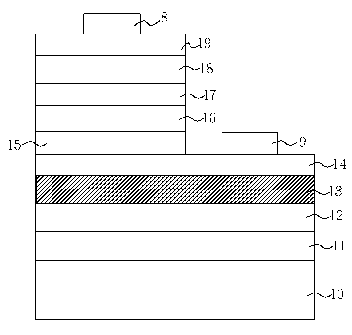
[0032]Please refer to FIG. 4, which is a diagram of an embodiment of an LED of an omnidirectional reflector providing with a transparent conductive layer according to the present invention. The LED comprises a substrate 10, an adhesive layer 11 formed on the substrate 10, a metal reflection layer 12 formed on the adhesive layer 11, a cohesion layer 13 formed on the metal reflection layer 12, a transparent conductive layer 14 formed on the cohesion layer 13, wherein the upper surface of the transparent layer 14 comprises a first surface area and a second surface area. The LED further comprises a first contact layer 15 formed on the first surface area, a first cladding layer 16 formed on the first contact layer 15, a light-emitting layer 17 formed on the first cladding layer 16, a second cladding layer 18 formed on the light-emitting layer 17, a second contact layer 19 formed on the second cladding layer 18, a first wire electrode 8 formed on the second contact layer 19, and a second ...

embodiment 2

[0033]Please refer to FIG. 5, which is a diagram of another embodiment of a flip-chip LED of an omnidirectional reflector providing with a transparent conductive layer according to the present invention. The flip-chip LED comprises a transparent substrate 110, a first contact layer 111 formed below the transparent substrate 110, wherein the bottom surface of the first contact layer 111 comprises a first surface area and a second surface area. The flip-chip LED further comprises a first cladding layer 112 formed below the first surface area of the first contact layer 111, a light-emitting layer 113 formed below the first cladding layer 112, a second cladding layer 114 formed below the light-emitting layer 113, a second contact layer 115 below the second cladding layer 114, a transparent conductive layer 14 formed below the second contact layer 114, a cohesion layer 116 having a distributed geometrical pattern formed below the transparent conductive layer 14, a metal reflection layer ...

embodiment 3

[0034]Please refer to FIG. 6, which is a diagram of the other embodiment of a flip-chip LED having an omnidirectional reflector and a transparent conductive layer according to the present invention. In this embodiment, the flip-chip LED is similar to that of the above-mentioned embodiment. The difference between them is that the above-mentioned transparent substrate is a combination of a transparent substrate and an adhesive layer. In this embodiment, the flip-chip LED comprises a transparent substrate 110, an adhesive layer 111 formed below the transparent substrate 110, and a transparent conductive layer 14 formed below the adhesive layer 11, wherein the bottom surface of the transparent conductive layer 14 comprises a first surface area and a second surface area. The flip-chip LED further comprises a first contact layer 111 formed below the first surface area of the transparent conductive layer 14, a first cladding layer 112 formed below the first contact layer 111, a light-emitt...


PUM


Abstract

The present invention is related to a light emitting diode of an omnidirectional reflector providing with a transparent conductive layer. In the present invention, a cohesion layer is formed between a transparent layer and a metal reflection layer to improve the cohesive force therebetween and increase the reflectivity of the light emitting diode, so as the present invention can enhance the light-emitting efficiency of the light emitting diode.

Description

BACKGROUND OF THE INVENTION[0001]1. Field of the Invention[0002]The invention relates to a light-emitting diode having an omnidirectional reflector (ODR), and more particularly, to a light-emitting diode having an omnidirectional reflector including a transparent conductive layer.[0003]2. Description of the Related Art[0004]LEDs have broad applications. For example, LEDs can be utilized in optical displays, traffic signs, data storage devices, communication devices, lighting devices, and medical devices. Therefore, the luminance and lighting efficiency of an LED has become an important consideration in LED production.[0005]In Proc. SPIE Int. Soc. Opt. Eng. 4996 139 (2003) of Gessmann, an LED having an omnidirectional reflector and its producing method is disclosed. A GaN LED stack is formed on a sapphire substrate, an ITO transparent conductive layer is formed on the GaN LED stack, and an Ag layer is formed on the ITO transparent conductive layer. A GaN / ITO / Ag ODR-LED structure is t...

Claims


Application Information

Patent Timeline
Patent Type & Authority Patents(United States)
IPC IPC(8): H01L33/00H01L33/32H01L33/42
CPCH01L33/46
Inventor HSIEH, MIN-HSUNTAO, CHING-SANTSENG, TZU-FENGNI, JR-PENG
Owner EPISTAR CORP
Why Eureka
Try Eureka