
Method in microscopy and a microscope, where subimages are recorded and puzzled in the same coordinate system to enable a precise positioning of the microscope stage

Active Publication Date: 2008-02-05
CELLAVISION
View PDF11 Cites 16 Cited by
  • Summary
  • Abstract
  • Description
  • Claims
  • Application Information

AI Technical Summary

Benefits of technology

[0014]An advantage of this method is that a position can be determined without necessitating installation of special position sensors. Instead the position can be determined by means of the images which are recorded by the image sensor. The position can thus be obtained in an image coordinate system instead of, as before, in a coordinate system related to the microscope stage and its drive mechanism.
[0044]To reduce the calculation work, it has been found. advantageous to spatially filter the second image before the comparison with the first image which has then, of course, also been spatially filtered. An example of how spatial filtering can be carried out is disclosed in PCT / SE98 / 02380. The spatial filtering makes it possible to separate the registration so that it can be carried out for one of two orthogonal directions at a time.

Problems solved by technology

A hardware component which is relatively expensive is the microscope stage with its drive mechanism.
The accuracy with which the position is found again is not allowed to be too poor.
However, such components are quite expensive.
The drawback of this is, however, that it will be necessary to install additional components which can break, increase the cost of the microscope and need space.
However, this requires a repeatable drive mechanism for the microscope stage, which has up to now been provided using expensive screws and stepping motors or position control with extra position sensors.

Method used


Image

  • Method in microscopy and a microscope, where subimages are recorded and puzzled in the same coordinate system to enable a precise positioning of the microscope stage
  • Method in microscopy and a microscope, where subimages are recorded and puzzled in the same coordinate system to enable a precise positioning of the microscope stage
  • Method in microscopy and a microscope, where subimages are recorded and puzzled in the same coordinate system to enable a precise positioning of the microscope stage

Examples


Embodiment Construction

Composition of the Microscope

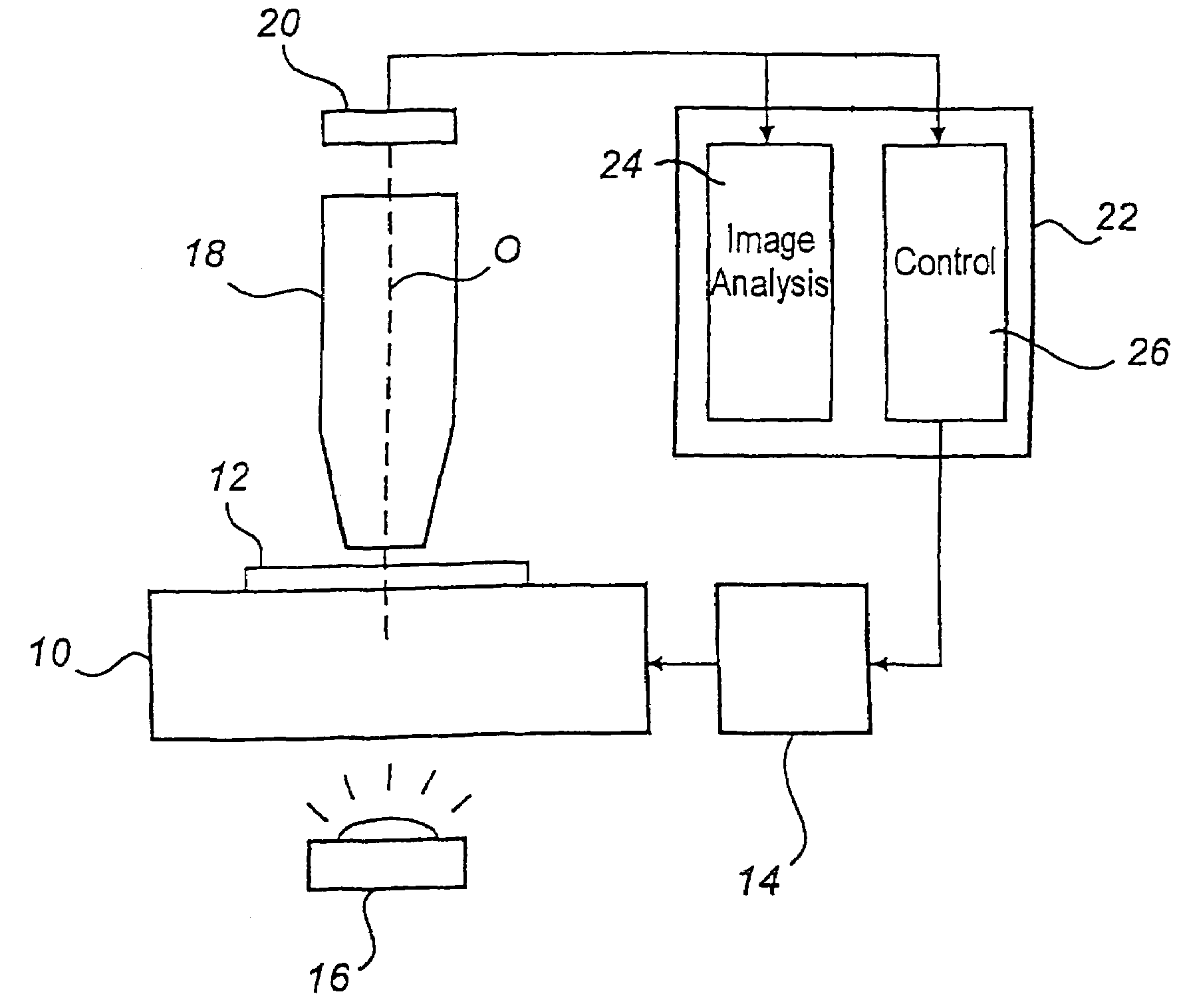
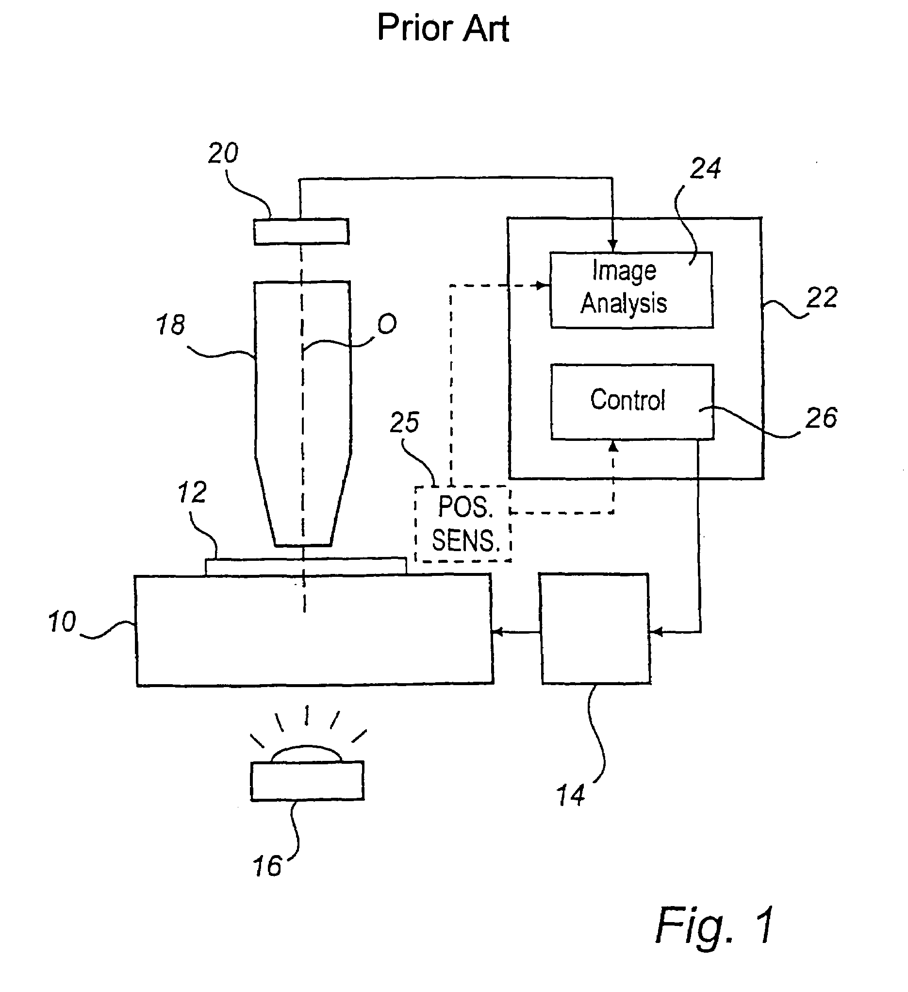
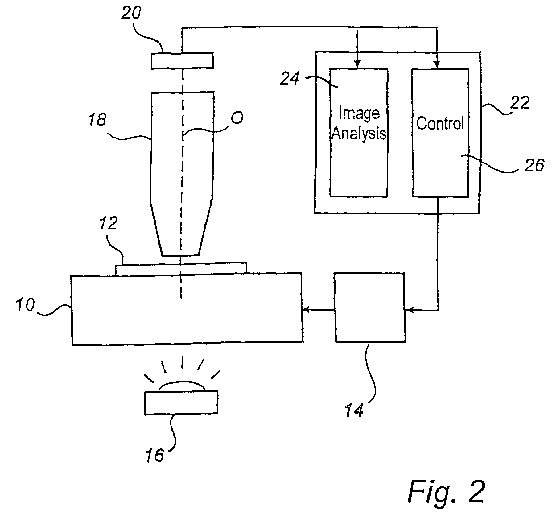
[0056]FIG. 2 shows schematically an example of a computer-aided microscope according to an embodiment of the invention. For parts corresponding to those in FIG. 1, the same reference numerals have been used as in FIG. 1.

[0057]The microscope, which can be, for example, a light field microscope, a dark field microscope or a phase contrast microscope comprises the following main components: a microscope stage 10 for carrying an object 12, a drive mechanism 14 for the microscope stage, an illumination device 16 for illuminating the object, an objective 18 for reproducing the object, an image sensor 20 for recording an image of the object, and a computer 22 for processing and storage of image data and for controlling the drive mechanism. The microscope can also be provided with other components (not shown) which are usually to be found on a microscope, such as an eyepiece , knobs for manual displacement of the microscope stage and components for manual and co...


PUM


Abstract

In a microscope, a position signal is generated in the form of coordinates in a pixel coordinate system by registering microscope images with partly overlapping contents. The position signal can be used to indicate the position of a partial object which has been identified in one of the microscope images. It can also be used to control the displacement of the microscope stage of the microscope, in which case it is possible to use a simple inaccurate drive mechanism for the microscope stage, without necessitating installation of position sensors.

Description

[0001]This is a national phase filing under 35 U.S.C. § 371 of International Application No. PCT / SE02 / 00719, filed Apr. 12, 2002, that designates the United States of America. The benefit is claimed under 35 U.S.C. § 119(a)-(d) of Swedish Application No. 0101319-2, filed Apr. 12, 2001, and under 35 U.S.C. § 119(e) of U.S. Provisional Application No. 60 / 286,792, filed Apr. 26, 2001.FIELD OF THE INVENTION[0002]The present invention relates to a method in microscopy, a computer program product with program code for implementing the method, and a microscope.BACKGROUND ART[0003]Computer-aided microscopes have previously been used above all in research activities, but are now being increasingly used in commercial applications. In this connection, it has become interesting to reduce the costs of such microscopes.[0004]FIG. 1 shows schematically an example of how a computer-aided microscope can be composed. The microscope comprises a movable microscope stage 10, on which the object 12 to be...

Claims


Application Information

Patent Timeline
IPC IPC(8): G06K9/32G02B21/00G02B21/26G06T7/00
CPCG02B21/26G06K9/00134G06T7/0034G02B21/367G06K2009/2045G06T2207/20012G06T2207/20016G06T2207/20068G06T2207/10056G06T7/35G06V20/693G06V10/16G06T7/74G02B21/00G06T7/00G06V10/147G06V30/144
Inventor KARLSSON, ADAMLINDERUP, ERIK
Owner CELLAVISION
Learn More