Wireless network system and method

a wireless network and wireless network technology, applied in the field of wireless network systems and methods, can solve the problems of cellular systems requiring a significant infrastructure investment, system can typically only serve one or a limited number of users,

Active Publication Date: 2008-02-05
XYLON LLC
View PDF14 Cites 60 Cited by
  • Summary
  • Abstract
  • Description
  • Claims
  • Application Information

AI Technical Summary

Benefits of technology

[0016]Embodiments of the present invention provide a system and method for wireless communication that eliminates, or at least substantially reduces, the shortcomings of prior art systems and methods for “last-mile” wireless communication. More particularly, embodiments of the present invention provide a flexible system for providing wireless broadband access. The system can include a gateway that has a plurality of gateway premises equipment (“GPE”) units and a network fuser connected to the plurality of GPE units to coordinate the activities of the plurality of the GPE units. The network fuser can provide DSP configuration information and RF configuration information to the GPE units. The network fuser is also operable to connect to a high-speed network (e.g., a backhaul network) and to provision data from the high-speed network to each of the plurality of GPE units. The system can also include a plurality of customer premises equipment (“CPE”) units remote from the gateway. Each GPE unit can establish a wireless communications link, such as a MIMO link, with at least one CPE unit to wirelessly transfer data. According to one embodiment of the present invention, the GPE units and CPE units can have the same architecture to reduce cost.

Problems solved by technology

These systems can typically only serve one or a limited number of users.
However, cellular systems require a significant infrastructure investment.

Method used


Image

  • Wireless network system and method
  • Wireless network system and method
  • Wireless network system and method

Examples


Embodiment Construction

[0049]Embodiments of the present invention provide a flexible architecture for provisioning of data via a wireless communications link.

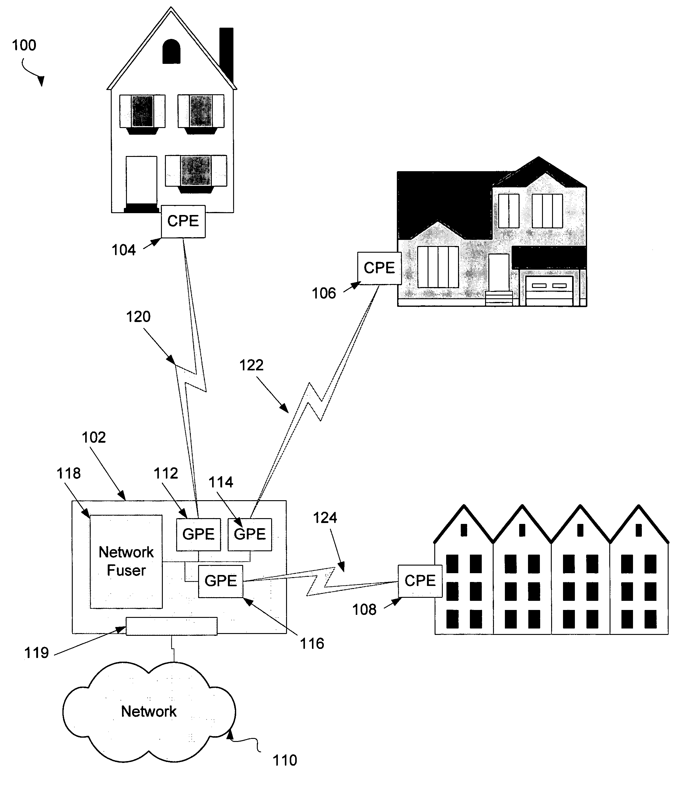
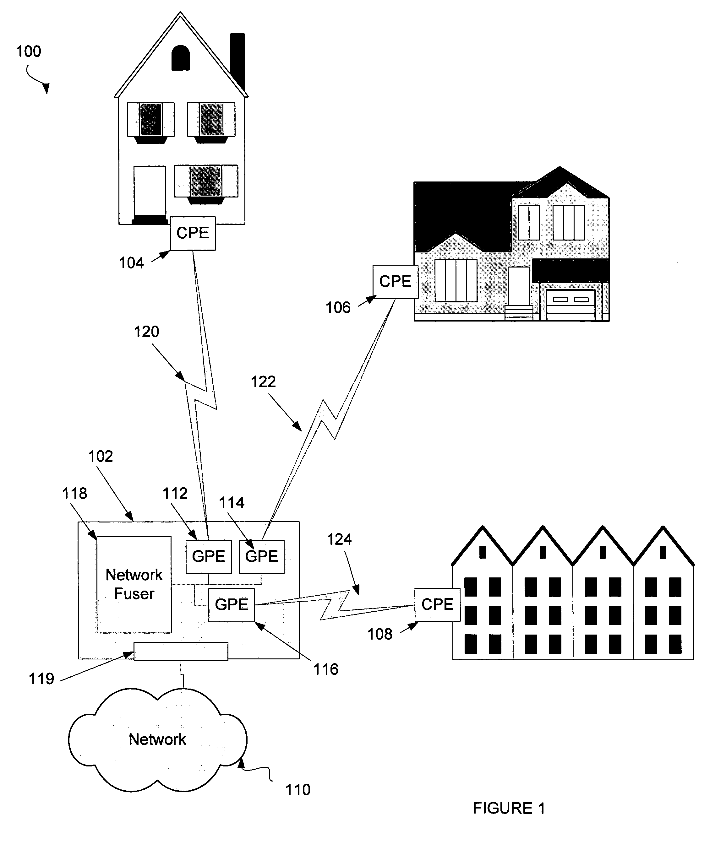
[0050]FIG. 1 illustrates one embodiment of a communications network 100 for providing a wireless high-speed communications link. FIG. 1 depicts provisioning of wireless access to end-users (i.e., “last mile” provisioning). The system 100 comprises a gateway 102, several sets of customer premises equipment (“CPE”) (CPE 104, CPE 106, CPE 108) and a data transport network 110 (e.g., Ethernet, the Internet, a wireless network or any data network known in the art). It should be noted that the term “customer premises equipment” is simply used to refer to equipment that can wirelessly communicate with gateway 102. According to one embodiment of the present invention, network 110 can be a high-speed network 110. Gateway 102 can include gateway premises equipment (“GPE”) 112, 114 and 116, network fuser 118, and a connection 119 to data transport network 110. ...


PUM


Abstract

Embodiments of the present invention provide a flexible system for providing wireless broadband access. The system can include a gateway that has a plurality of gateway premises equipment (“GPE”) units and a network fuser connected to the plurality of GPE units to coordinate the activities of the plurality of the GPE units. The network fuser can provide DSP configuration information and RF configuration information to the GPE units. The network fuser is also operable to connect to a high-speed network (e.g., a backhaul network) and to provision data from the high-speed network to each of the plurality of GPE units. The system can also include a plurality of customer premises equipment (“CPE”) units remote from the gateway.

Description

RELATED APPLICATIONS[0001]The present application claims priority under 35 U.S.C. §119(e) to U.S. Provisional Application No. 60 / 508,193 entitled “A Flexible MIMO-Based Last Mile Wireless Network System and Method” by Heath et al., filed Oct. 2, 2003 and U.S. Provisional Patent Application No. 60 / 513,273, filed Oct. 1, 2003, entitled “A Flexible MIMO-Based Last Mile Wireless Network System and Method” by Heath et al., both of which are hereby fully incorporated by reference herein.BACKGROUND[0002]Wireless communication networks have enjoyed rapid growth in recent years, as evidenced by the rapid deployment of IEEE 802.11 a / b / g networks and the adoption of 2.5 G and 3 G cellular telephone networks. These wireless networks are now used throughout the world. 802.11 a / b / g networks provide an advantage of working in a band of the radio spectrum currently unlicensed in the United States, as described in Rappaport, Wireless Communications, Prentice Hall c. 2002. The use of the unlicensed s...

Claims


Application Information

Patent Timeline
Patent Type & Authority Patents(United States)
IPC IPC(8): H04L1/00G01R31/08G06F11/00G08C15/00H04B1/38H04B7/00H04J1/16H04J3/14H04LH04L12/26H04M1/00H04W84/10H04W88/12
CPCH04B7/0413H04W88/12H04B7/0617H04B7/0669H04B7/068H04B7/10H04W84/10
Inventor RAPPAPORT, THEODORE S.HEATH, ROBERT W.
Owner XYLON LLC
Why Eureka
Try Eureka