Optical transmission device and electronic apparatus

a transmission device and electronic equipment technology, applied in the direction of instruments, recording information storage, disposition/mounting of heads, etc., can solve the problems of insufficient reduction of the number of parts and complexity of the assembly structure of the optical transmission device, and achieve the effects of high production efficiency, simple handling and easy assembly

Active Publication Date: 2008-02-12
SHARP KK +1
View PDF11 Cites 8 Cited by
  • Summary
  • Abstract
  • Description
  • Claims
  • Application Information

AI Technical Summary

Benefits of technology

[0010]The present invention was made in view of the problems described above, and its object is to provide an optical transmission device that can be cheaply produced with a simple design, wherein the number of parts can be reduced. It is a further object of the invention to provide an optical transmission device that can more effectively succeed at preventing the invasion of dust and other foreign substances into the part that optically / mechanically joins the light receiving and transmitting portion with the plug portion of the fiber-optic cable, and at protecting eyes from light leakage, which were objects of the conventional technology.

Problems solved by technology

Therefore, the assembly structure of the optical transmission device is complicated, and the conventional technology has not arrived at a point where the number of parts can be adequately reduced.

Method used


Image

  • Optical transmission device and electronic apparatus
  • Optical transmission device and electronic apparatus
  • Optical transmission device and electronic apparatus

Examples


first embodiment

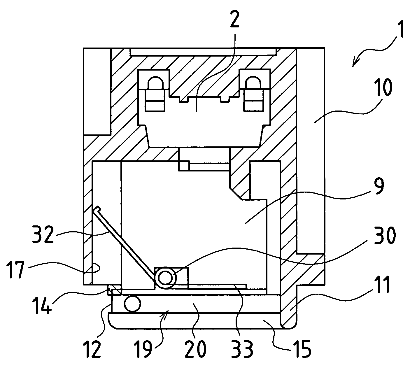
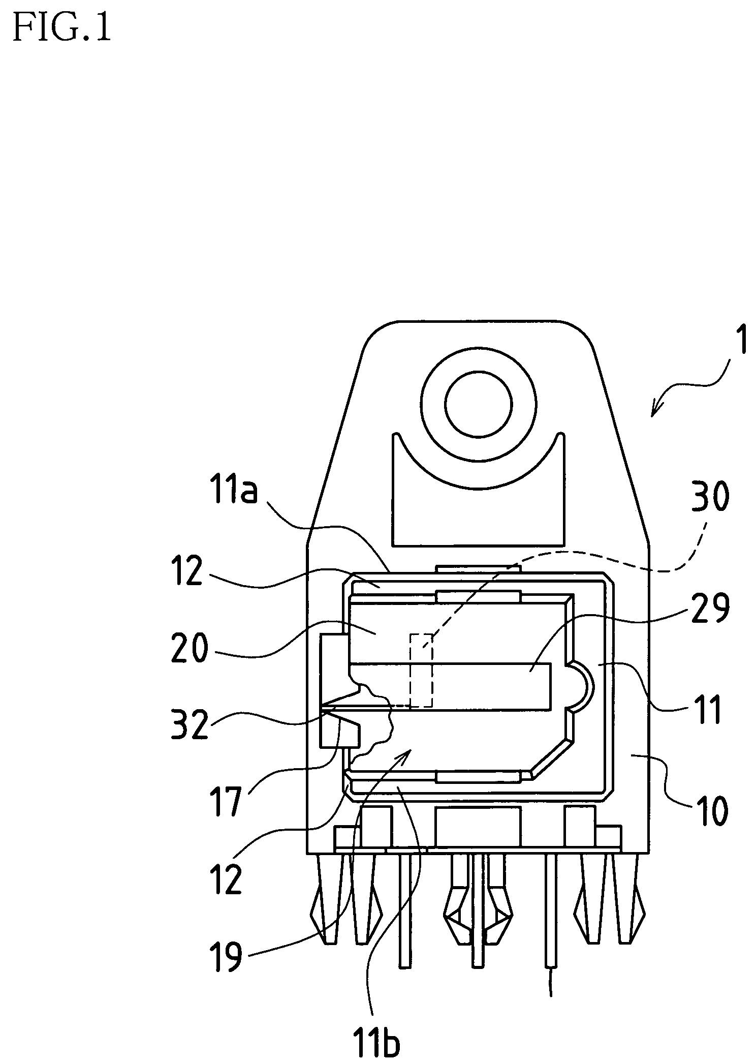
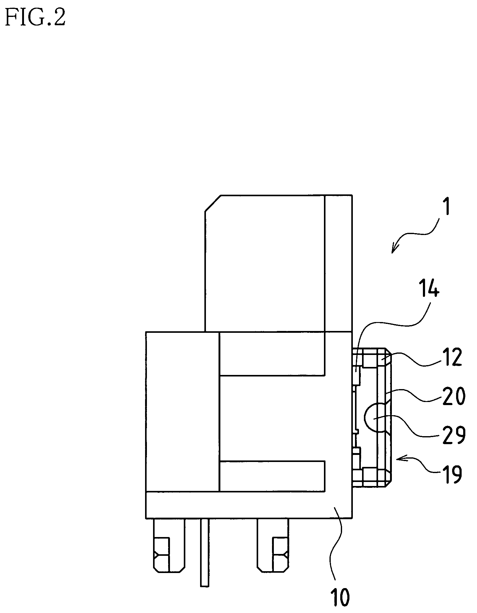
[0041]FIG. 1 is a front view of the optical transmission device of a first embodiment of the present invention, and FIG. 2 is a lateral view of the same. FIG. 3A is a cross-sectional plan view with the shutter in a closed state, and FIG. 3B is a cross-sectional plan view with the shutter in an open state.

[0042]As shown in FIGS. 1 through 3, an optical transmission device 1 of the present embodiment mainly comprises a single case 10 (hereinafter, referred to as “housing”) and a shutter mechanism 19. The case 10, which holds an optical element 2 that receives or transmits light, is provided with an insertion hole 15 into which a plug is inserted. The shutter mechanism 19 opens and closes this insertion hole 15. The shutter mechanism 19 comprises a shutter 20, and a torsion coil spring 30 as an elastic body that biases the shutter 20 in the direction closing the same.

[0043]The housing 10 is molded in one piece and is provided with a containing portion 9 that contains the optical elemen...

second embodiment

[0062]FIG. 9 shows the shutter mechanism 19 of a second embodiment of the present invention. FIG. 9A shows a shutter mechanism configured from a torsion coil spring with the shutter 20 and an elastic body configured as single body. The rotating shafts 24 have a function corresponding to the coil portion 31 of the torsion coil spring 30. The ends of the torsion coil spring that forms the rotating shafts 24 are fixed to the housing 10. By also forming the main shutter body 21 from the same member as the coil spring, because that member fulfills the role of the shutter, the shutter necessary up to now is not required.

[0063]As shown in FIGS. 9B and 9C, it is also possible to adapt a configuration in which the rotating shafts 24 of shutter 20, and a shutter frame 27, are configured from the torsion coil spring, and a resin plate corresponding to the main shutter body 21 is fitted to that frame 27.

third embodiment

[0064]A third embodiment of the present invention, shown in FIGS. 10A through C, is provided with a pair of hooks (holding protrusions) 28 on the rear side of shutter 21 that fit around and hold the coil portion 31 of the torsion coil spring 30. This third embodiment is easy to assemble, because the aforementioned support portion is not necessary. Also, the third embodiment of the present invention is configured with stoppers (protrusions for preventing positional displacement) 29 provided on the sides where there are no hooks 28, such that positional displacement of the torsion coil spring 30 does not occur.

[0065]FIGS. 11A through C show a modified example of the third embodiment. This modified example is structured with the holding arm 33 of the torsion coil spring 30 fitted and fixed to a holding portion 28a that protrudes from the rear side of the main shutter body 21, and is easy to assemble because the support portion is not necessary. Also, in this modified example, the protr...


PUM


Abstract

An optical transmission device configured from a case that holds an optical element that receives and / or transmits light, the case being provided with a plug insertion hole into which a plug for transmitting an optical signal is inserted; and a shutter mechanism having a shutter that opens and closes the plug insertion hole; wherein the case is provided with an installation part that holds the shutter such that it can rotate freely, and wherein the shutter mechanism can be installed from the outside to the installation part.

Description

BACKGROUND OF THE INVENTION[0001]1. Field of the Invention[0002]This application claims priority on Patent Application No. 2004-199649 filed in Japan on Jul. 6, 2004, the entire contents of which are hereby incorporated by reference.[0003]The present invention relates to optical transmission devices used in electronic equipment such as DVD players, DVD recorders, televisions, and set-top boxes, as well as audio-video receivers, personal computers, PDAs, mobile phones and the like; and further relates to electronic apparatuses.[0004]2. Description of the Related Art[0005]In recent years, in household equipment of which DVD is representative, digital audio signal transmission by optical signals is becoming widespread. The receiving and transmitting portions of such digital audio signal transmission are provided with a mechanism that, when signal transmission is not performed, prevent the invasion of dust and other foreign substances into the part where the light receiving and transmit...

Claims


Application Information

Patent Timeline
Patent Type & Authority Patents(United States)
IPC IPC(8): G02B6/36
CPCG11B7/10G11B7/1201G11B7/1205G02B6/3897G11B7/121G11B7/123G02B6/4278
Inventor SOHMURA, ATSUSHIMIZUNO, HIROSHIIKUTA, MITSUHISAMITSUMOTO, KAZUHIROUMEKI, SHIGERU
Owner SHARP KK
Why Eureka
Try Eureka