Aerodynamic-hybrid vertical-axis wind turbine

a vertical-axis wind turbine and hybrid technology, applied in the direction of electric generator control, renewable energy generation, greenhouse gas reduction, etc., can solve the problems of crippling the enormous potential of the vertical-axis wind turbine, neither of the devices employ rotor airfoils that exhibit bidirectional characteristics, and suffer from the effects of salient back pressure, effectively and efficiently harnessing

Inactive Publication Date: 2008-02-12
NOVASTRON
View PDF28 Cites 104 Cited by
  • Summary
  • Abstract
  • Description
  • Claims
  • Application Information

AI Technical Summary

Benefits of technology

[0058]The present invention provides a novel, scientifically founded, means of inducing maximal energy transition torque on a stackable, vertical-axis, aerodynamic-hybrid wind turbine apparatus, over the entire 360 degrees of rotation, by eliminating salient back pressure while effectively and efficiently harnessing both aerodynamic lift and drag forces, in an embodiment employing consummate, stator and rotor, bidirectional airfoils, without regard for horizontal wind orientation. Furthermore, the unique design innovations of the present invention resolve the inherent underlying disadvantages encountered with prior art designs, resulting in an environmentally friendly device exhibiting energy extraction capabilities that border the currently understood theoretical limits, over an extended range of wind velocities and / or altitudes, and unrivaled implementation flexibility.

Problems solved by technology

Unfortunately, prior art vertical-axis wind turbines have suffered from fundamental design flaws, crippling their enormous latent potential.
However, neither of these devices employ rotor airfoils that exhibit bidirectional characteristics.
The primary consequence of a unidirectional blade, employed within a vertical-axis wind turbine device, is increased turbulence and muted efficiency.
Moreover, due to the hook shape of Pechler's rotor blades, and the prominent bulges associated with the Gual blades, as wind exits past these blades turbulence will ensue, and laminar flow potential will be greatly diminished.
Moreover, the Gual patent has stator blades that are asymmetrical, and therefore, not uniformly convex.
This design attribute will inevitably produce a bow shock on the proximal side of the wind stream, substantially throttling aerodynamic efficiencies, while concurrently producing increased turbulence distally.
These ducts serve to equalize the air pressure on both the leading and trailing sides of the blades; thereby, aerodynamic lift potential is abandoned in favor of less efficient thrust mechanisms—aerodynamic lift is a coextensive byproduct of dissimilar air pressures that are induced upon opposite sides of an airfoil.
Furthermore, placing more than three rotor airfoils on a single tier effectually closes off the center of the rotor, and a proportionate reduction in aerodynamic lift potential ultimately results.
Even though the stator blades do reduce back pressure, while providing a novel means for effectively transferring torque to the rotor cups, during both their advance and return phase of rotation, they are not adequate to optimally provide this essential function omni-directionally.
These blades do not qualify as effective bidirectional airfoils, and therefore, are not conducive to the laminar conduction of wind through or around the device.
The invariant hemicyclic arcs of the rotor cups do minimize drag on their convex side; however, this shape is not a paragon for either harnessing or discharging the wind as it flows through the device.
These blades are not highly efficient bidirectional airfoils, and therefore are not conducive to the laminar flow of wind through the device.
Furthermore, because the harnessed wind cannot be released as early as would be ideal, downstream laminar flow potential is diminished.
However, their roughly equivalent structural proportion ratios attempt to compress oncoming wind well beyond the known theoretical limits of Betz Law, resulting in a bow shock on the proximal side of the device, and increased turbulence distally.
This unfavorable effect occurs, to some degree, even while operating under low wind speed conditions.
However, testing conclusively revealed the primary disadvantages of this paradigm to be turbulence, noise, and muted efficiency resulting from the non-bidirectional characteristics of the blades.
Consequently, wind became turbulent either upon entering or exiting these developmental predecessors.

Method used


Image

  • Aerodynamic-hybrid vertical-axis wind turbine
  • Aerodynamic-hybrid vertical-axis wind turbine
  • Aerodynamic-hybrid vertical-axis wind turbine

Examples


Embodiment Construction

[0077]Reference will now be made to the exemplary embodiments illustrated in the drawings, and specific language will be used herein to describe the same. It will nevertheless be understood that no limitation of the scope of the invention is thereby intended. Alterations and further modifications of the inventive features illustrated herein, and additional applications of the principles of the inventions as illustrated herein, which would occur to one skilled in the relevant art and having possession of this disclosure, are to be considered within the scope of the invention.

[0078]Various aspects of vertical axis wind turbines are discussed in U.S. Pat. No. 6,020,725 to Roberts and U.S. Pat. No. 6,465,899 to Roberts, which are incorporated by reference.

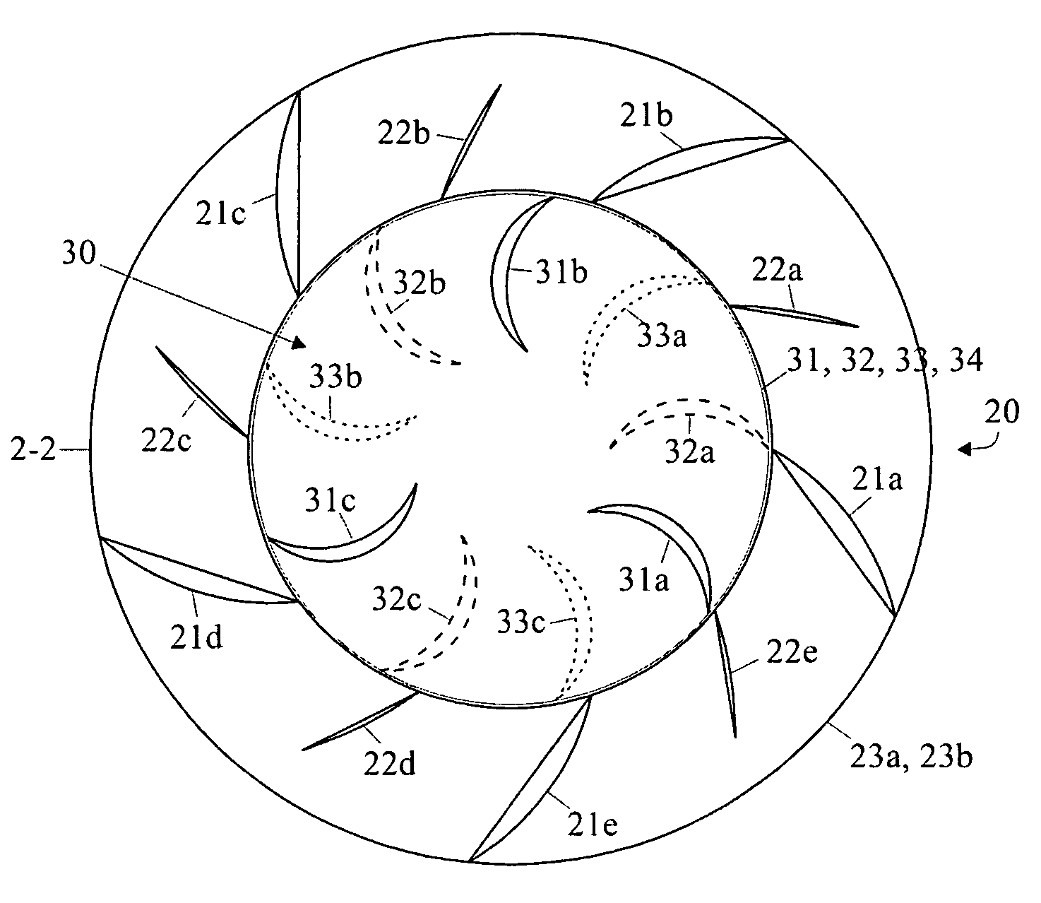
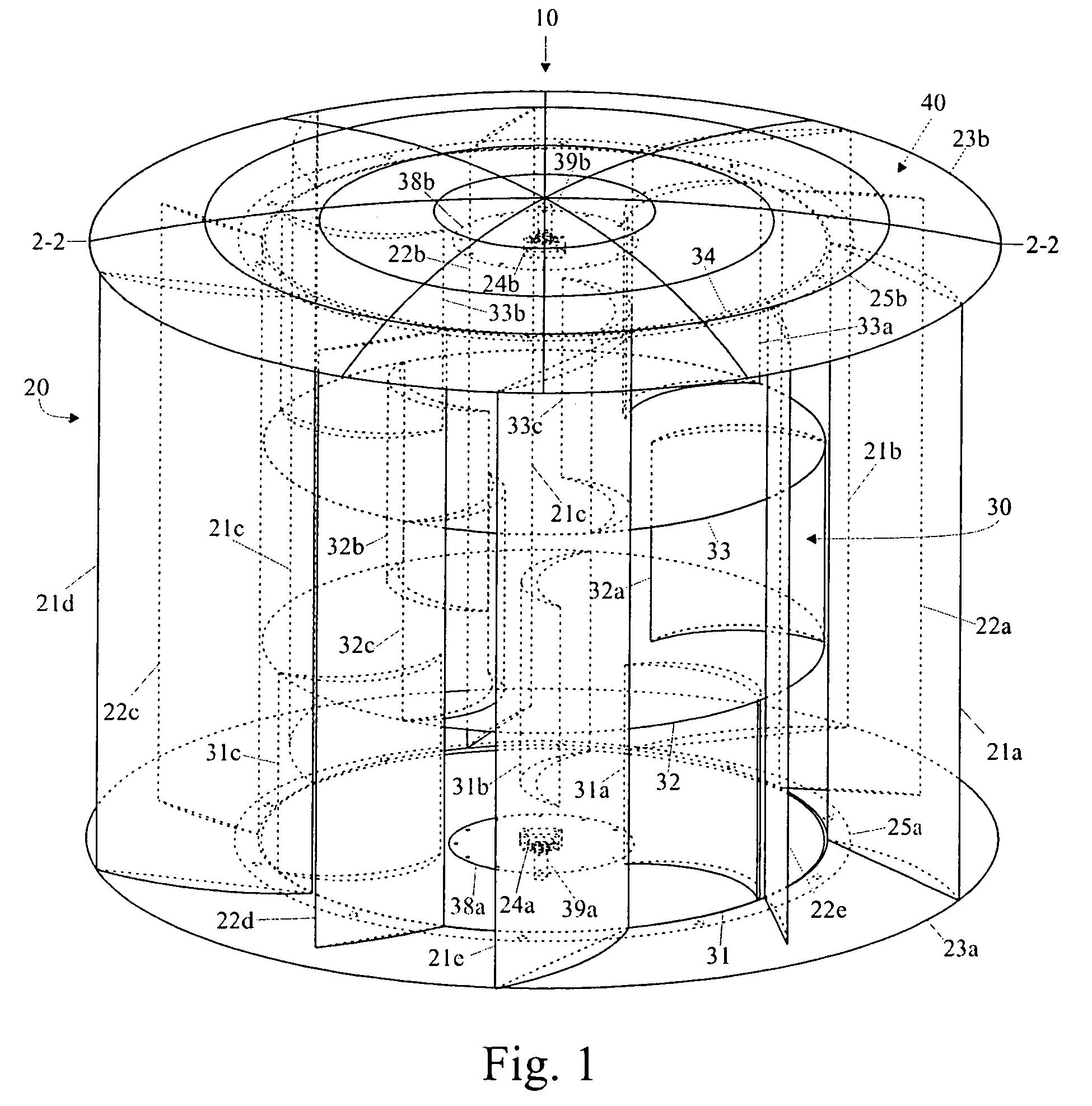
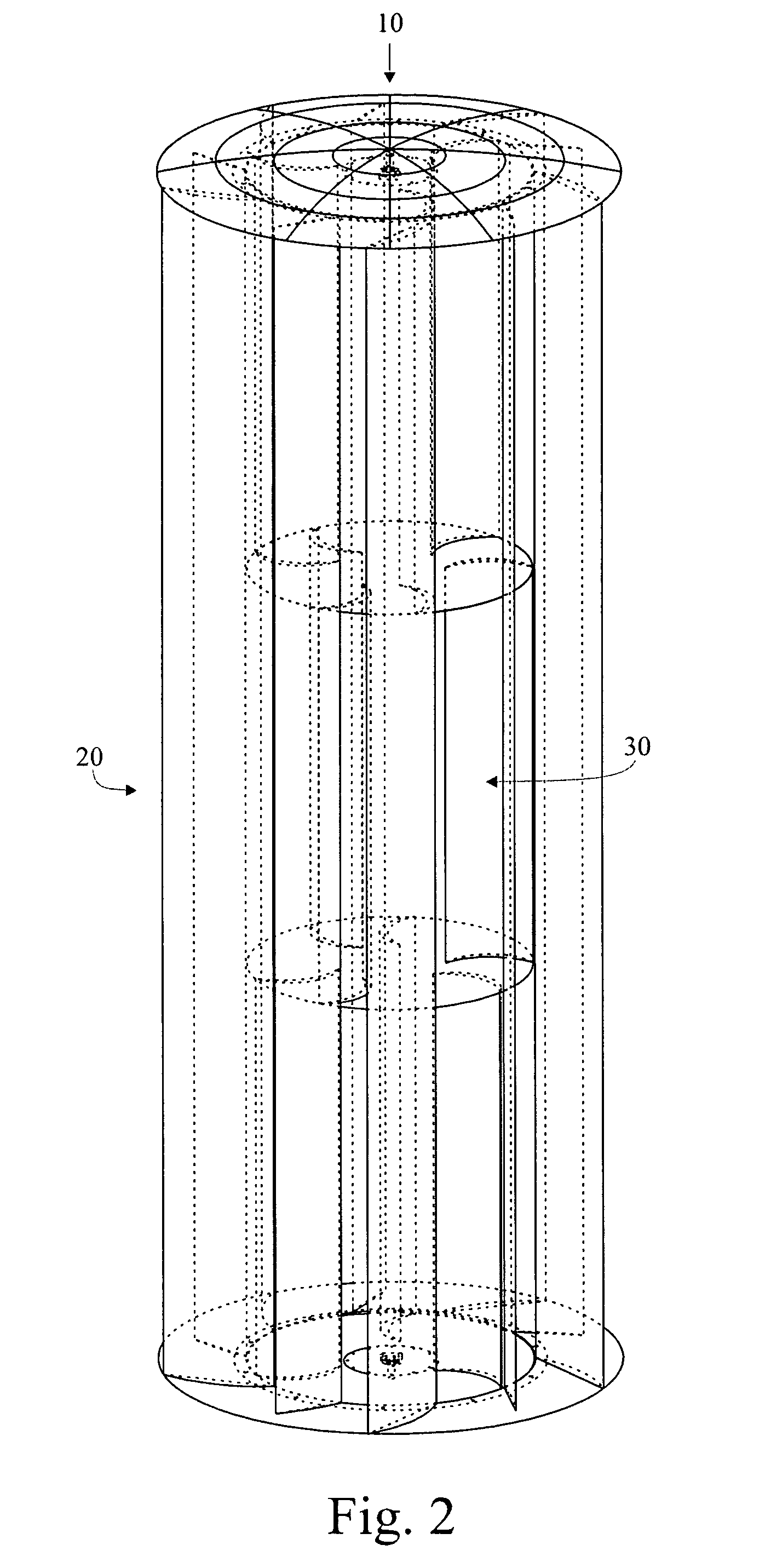
[0079]Referring more particularly now to the drawings of the present invention, FIG. 1 exemplifies a vertical-axis aerodynamic-hybrid wind turbine 10, having an intentionally open-ended mounting strategy. The turbine includes an annula...


PUM


Abstract

An aerodynamic-hybrid, vertical-axis wind turbine which includes a rotor airfoil and stator blade combination which maximizes energy production by increasing wind velocity and pressure while eliminating back pressure and improving the laminar flow of wind both around and through the device. The rotor airfoils have a horizontal cross-section with a crescent shape including a convex leading side and a concave trailing side with a thicker middle section that tapers to narrower sections at ends. The stator blades have a horizontal cross-section with a planar side and a convex side. Rotor airfoil and stator blade combinations are secured between upper and lower annular sails.

Description

BACKGROUND OF THE INVENTION[0001]1. Field of the Invention[0002]The present invention relates generally to generation of electricity by wind driven generators. More particularly, the present invention is a vertical axis wind turbine configured to efficiently harvest energy from the wind.[0003]2. Related Art[0004]Given the current global energy crisis, increased political tension with the world's largest petroleum suppliers, and the deleterious effects that fossil fuels have on the environment, renewable energy resources, including wind, are rapidly becoming less “alternative” and more an indispensable fact of life. Properly designed, a vertical-axis wind turbine features several distinct advantages over their horizontal-axis counterparts including increased safety, reduced environmental issues, and ameliorated location insensitivity to name only a few of the more conspicuous advantages.[0005]Unfortunately, prior art vertical-axis wind turbines have suffered from fundamental design f...

Claims


Application Information

Patent Timeline
Patent Type & Authority Patents(United States)
IPC IPC(8): F03D9/00H02P9/04
CPCF03D3/02F03D3/061F03D11/0025F05B2240/217Y02E10/74F03D80/40Y02E10/728F03D3/0409F03D80/70F03D13/20
Inventor ROBERTS, GARY D.ROBERTS, DAVID W.
Owner NOVASTRON
Why Eureka
Try Eureka