Electronic device including interface terminal and power supply cable connected thereto

Inactive Publication Date: 2008-02-12
TEAC CORP
View PDF3 Cites 13 Cited by
  • Summary
  • Abstract
  • Description
  • Claims
  • Application Information

AI Technical Summary

Benefits of technology

[0012]The present invention aims to solve such problem and to provide an electronic device that can easily receive electric current exceeding the maximum p

Problems solved by technology

However, since such configuration forces a user to spend time and effort installing the device driver in the host equipment, usability deteriorates.
There is also the case in which the installation of the software fails depending on a user, and it becomes impossible to provide a stable operation for the user.
Moreover, the configuration of the device driver that is installed on the host equipment side and of the firmware that operates on the USB device side becomes complicated an

Method used


Image

  • Electronic device including interface terminal and power supply cable connected thereto
  • Electronic device including interface terminal and power supply cable connected thereto
  • Electronic device including interface terminal and power supply cable connected thereto

Examples


embodiment 1

[Configuration of Device]

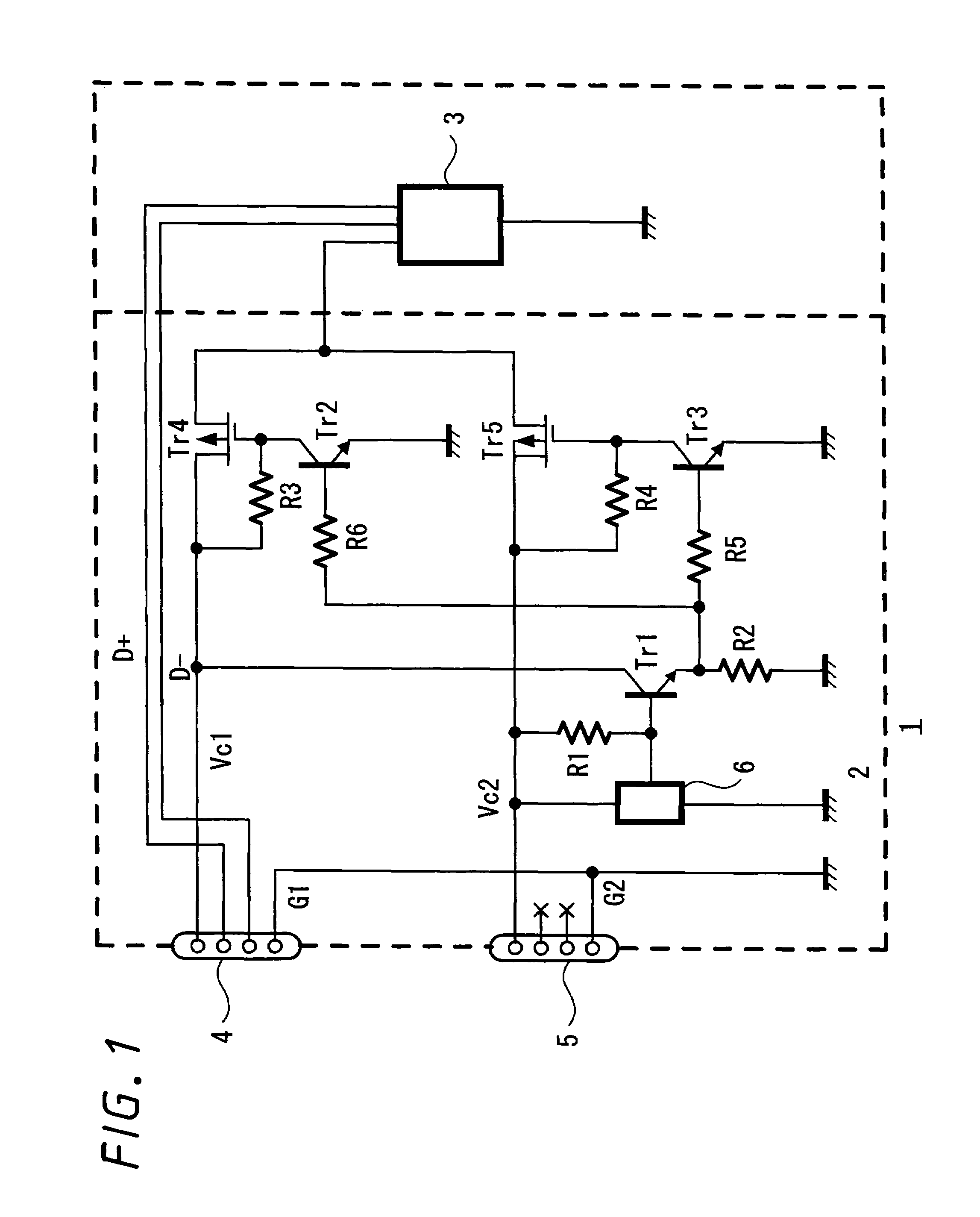
[0060]Hereinafter, embodiments of the present invention will be explained in detail by referring to the drawings. FIG. 1 is a power supply circuit of a USB device according to an embodiment of the present invention. A USB device 1 includes a power supply circuit 2 and a USB main unit 3. In the power supply circuit 2, a power supply cable Vc1 of a first USB cable 4 and a ground cable G1 are connected, and also, a power supply cable Vc2 of a second USB cable 5 and a ground cable G2 are connected to supply the following USB main unit 3 with power.

[0061]The USB main unit 3 constitutes known USB equipment such as a device having comparatively high consumption current, as well as being frequently used in combination with a notebook type personal computer or the like, for example, an optical disc apparatus such as a CD-RW drive or a DVD-RW drive. Although the USB main unit 3 is designed within a range where the consumption current does not exceed 1A, there is also ...

embodiment 2

[Configuration of Apparatus]

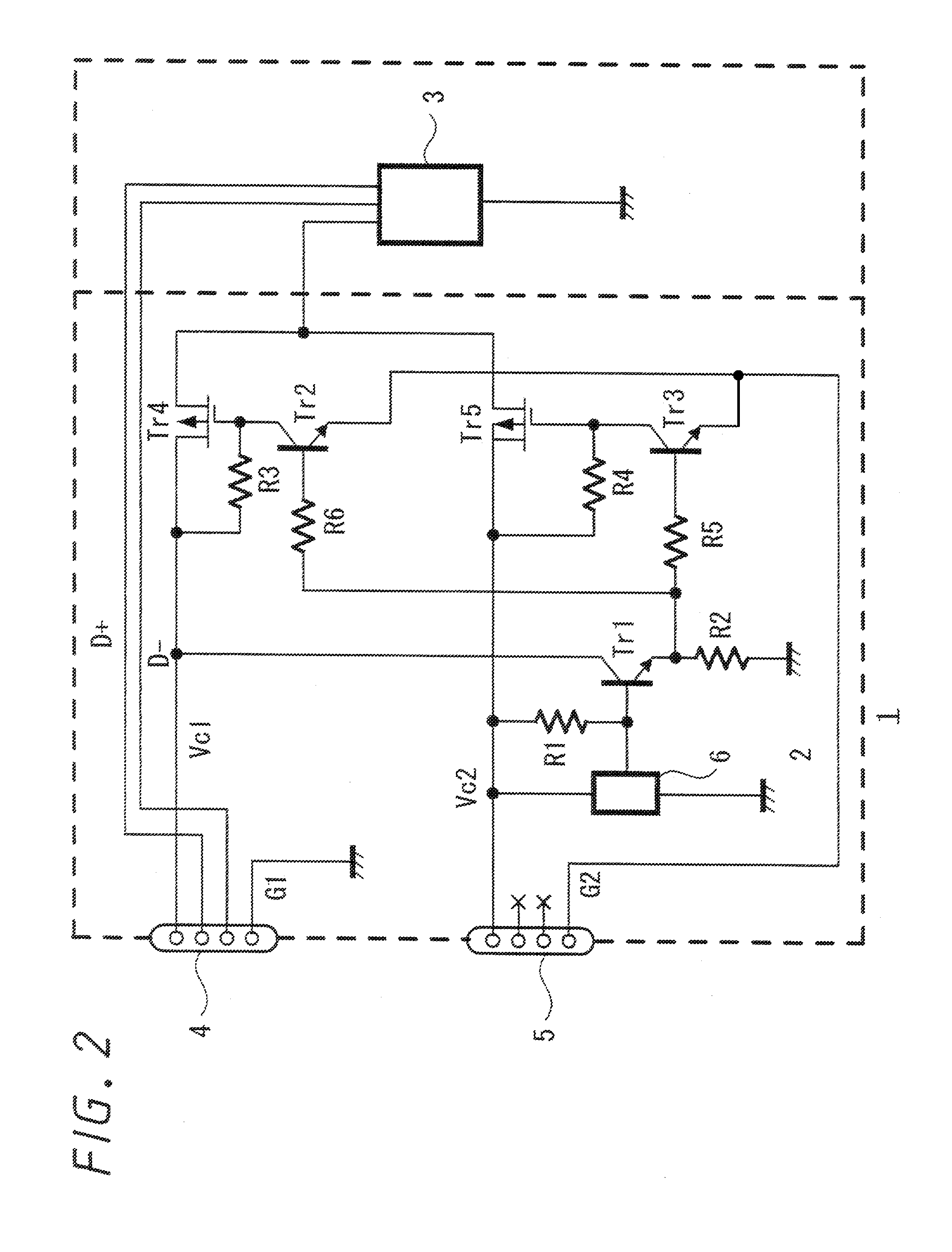
[0074]FIG. 2 is a power supply circuit of a USB device according to an embodiment of the present invention. An explanation regarding the same parts and functions as those in FIG. 1 is omitted and only the different parts from FIG. 1 will be explained. The ground cable G2 of the second USB cable is not connected to ground but is connected to the emitters of the transistor switches tr2 and Tr3. When the second USB cable 5 is connected to host equipment, the emitters of the transistor switches Tr2 and Tr3 are connected to the ground cable G1 of the first USB cable 4 through the ground of the host equipment.

[Operation]

[0075]In a state where the first USB cable 4 is connected to the host equipment and the second USB cable 5 is not connected to the host equipment, +5V is applied to the power supply cable Vc1, however +5V is not applied to the power supply cable Vc2. Accordingly, Tr1 is OFF since the voltage detection circuit 6 does not operate and the base pote...

embodiment 3

[Configuration of Apparatus]

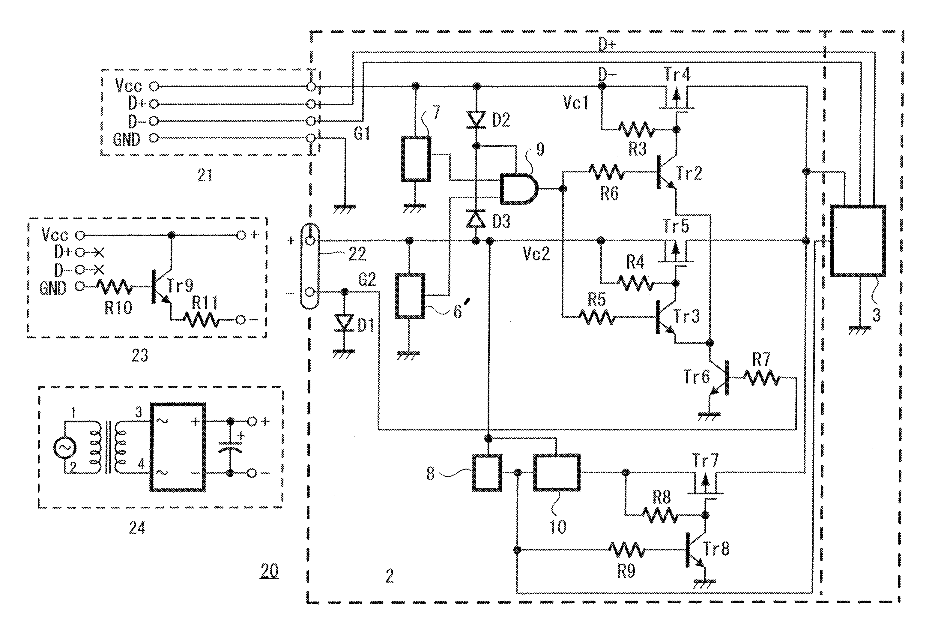
[0082]FIG. 3 is an overall view of a USB device according to an embodiment of the present invention, and FIG. 4 is a power supply circuit of the USB device according to an embodiment of the present invention. A DVD-RW apparatus 20 is provided with a USB cable 21 and a DC jack 22. The DC jack 22 is a known jack for a direct-current power supply to which an AC adaptor 24 and a USB conversion cable 23 are selectively connected. The AC adaptor 24 is a known AC-DC converter including a transformer, a diode rectifier, a capacitor and a coil, and outputs a voltage higher than bus power through a DC plug 24a. For example, a voltage of +9V is output. The USB conversion cable 23 is a conversion cable to connect a power supply cable of a USB interface to the DC jack 22 of the DVD-RW apparatus 20 and includes a USB plug 23a and a DC plug 23b when viewing the external appearance. A PNP transistor Tr9 for switching, a resistance R10 and a resistance R11 are provided in...


PUM


Abstract

It is difficult to increase consumption current of a bus-powered USB device. In order to solve this problem, a conversion cable for a DC connector and a USB connector is adopted in a USB device provided with a USB cable and a DC connector; a state in which power supply voltage is supplied to two sets of USB cables is detected; and a transistor power supply switch is turned on with a logical product thereof. An identification circuit which raises the potential of ground is incorporated in a USB conversion cable to be distinguished from an AC adaptor. When the AC adaptor is connected, the USB device operates as a self-powered USB device.

Description

BACKGROUND OF THE INVENTION[0001]1. Field of the Invention[0002]The present invention relates to an electronic device including an interface such as a USB, for example. Particularly, the present invention relates to an electric power supply section thereof.[0003]2. Description of the Related Art[0004]Hitherto, an electrical device including a USB (Universal Serial Bus) terminal (port), for example, such as a mouse, a keyboard, a CD-ROM, a CD-R / RW, an MO, and a DVD, has been known.[0005]Using the USB interface, not only transmission and reception of data but also an electrical power supply from a host to a device is possible, and such device is called a bus-power device. In the bus-power device, a low power device having consumption current of maximum 100 mA and a high power device having consumption current of maximum 500 mA are defined. In addition, a device including its own power supply means such as an external power source is correspondingly called a self-power device.[0006]As ...

Claims


Application Information

Patent Timeline
IPC IPC(8): H01H83/14H02H3/24G06F1/26H01R31/06
CPCG06F1/263G06F1/266H01R31/065
Inventor NIINUMA, SUSUMU
Owner TEAC CORP
Why Eureka
Try Eureka