LED package with non-bonded optical element

Inactive Publication Date: 2008-02-12
3M INNOVATIVE PROPERTIES CO
View PDF57 Cites 86 Cited by
  • Summary
  • Abstract
  • Description
  • Claims
  • Application Information

AI Technical Summary

Benefits of technology

[0007]Although advancements have been made, LEDs still have potential to be even brighter. It would be advantageous to have an LED package which allows light to be efficiently extracted from the LED die, and to maintain both high brightness and high luminous output. The present application discloses light sources that utilize LED dies

Problems solved by technology

Unfortunately, LEDs produce light in semiconductor materials, which have a high refractive index, thus making it difficult to efficiently extract light from the LED without substantially reducing brightness, or increasing the apparent emitting area of the LED.
A disadvantage of this approach

Method used


Image

  • LED package with non-bonded optical element
  • LED package with non-bonded optical element
  • LED package with non-bonded optical element

Examples


Embodiment Construction

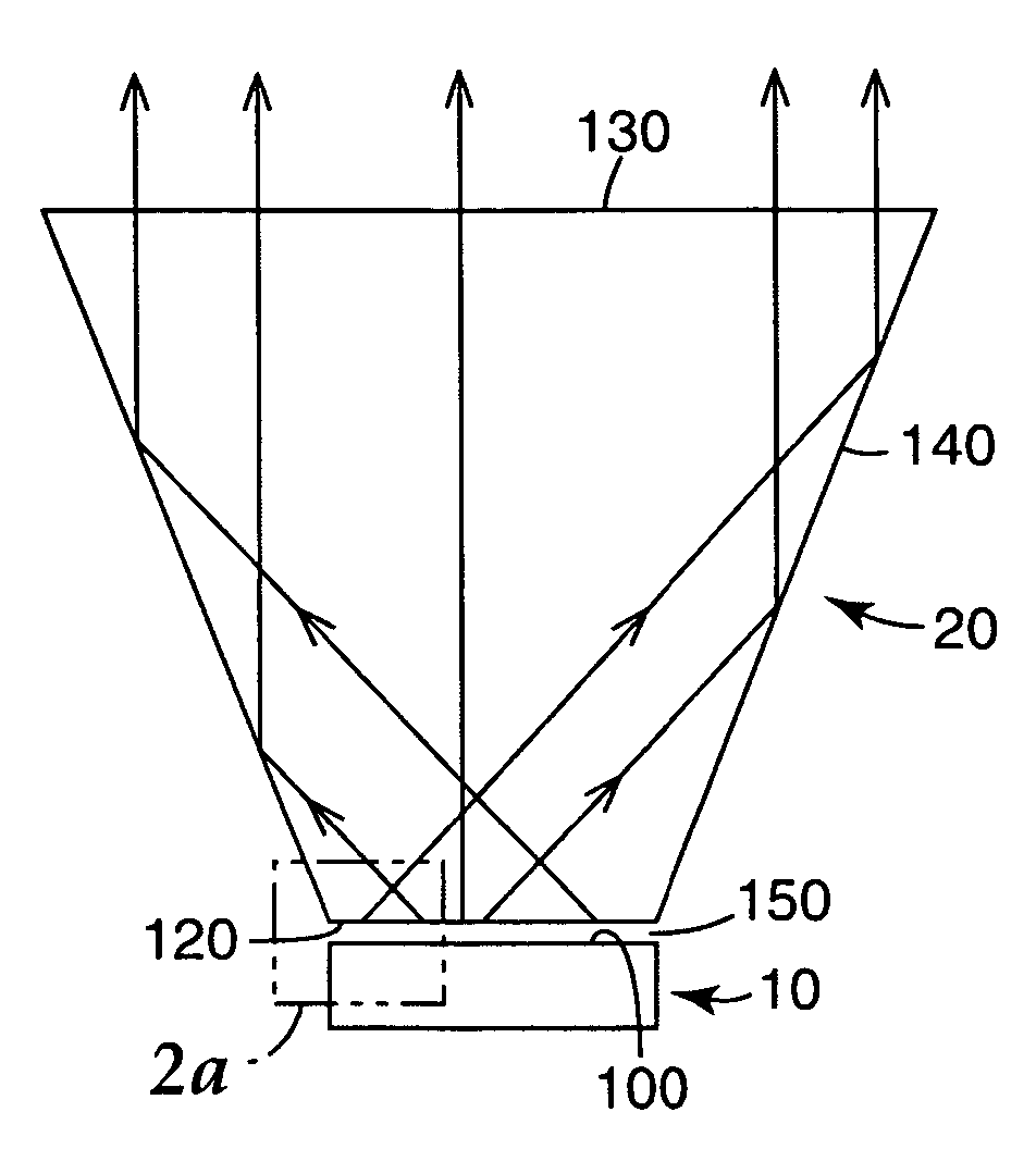
[0021]As described in more detail below, the present system provides a light source with an optical element for efficiently extracting light out of an LED die by modifying the angular distribution of light emitted by the LED die. The optical element is optically coupled to the emitting surface an LED die to efficiently extract light.

[0022]In some embodiments, the optical element is also thermally coupled to the LED die to permit heat removal from the LED die. To further extract heat away from the optical element, a thermally coupled heat sink clamp is added.

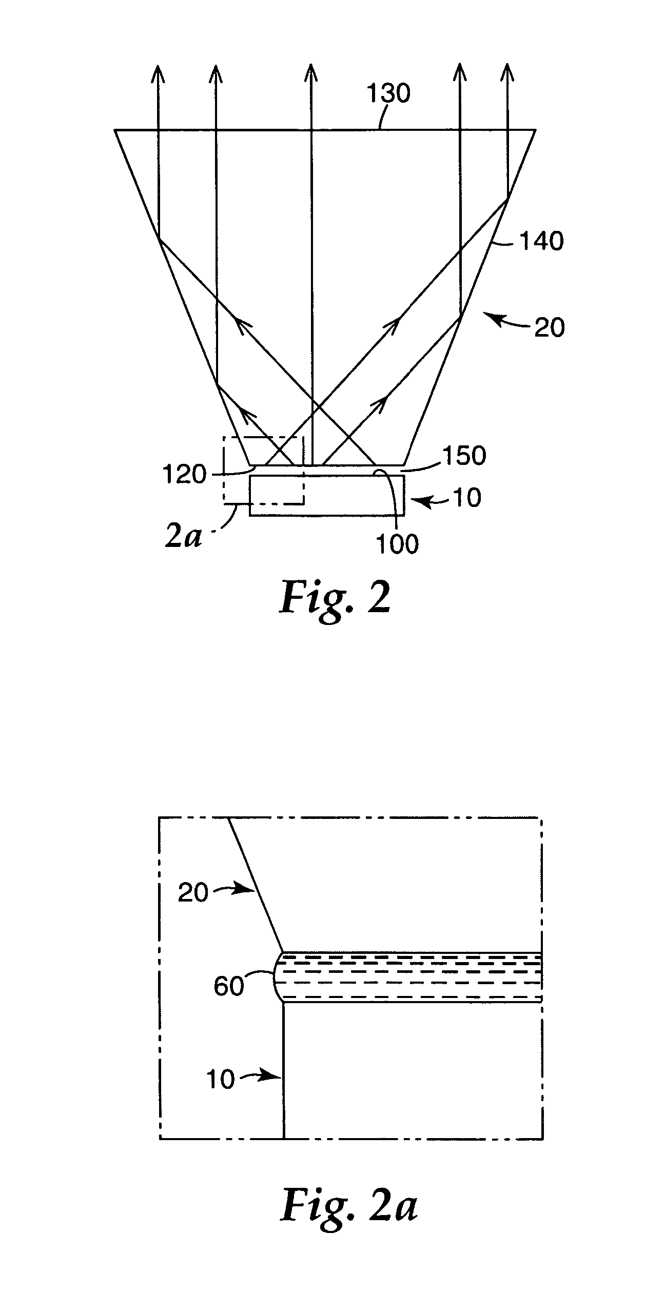
[0023]In other embodiments, an LED die is optically coupled to the optical element without use of any adhesives or other bonding agents between the LED die and the optical element. This allows the optical element and the LED die to move independently as they each expand when heated during operation. Absence of a bond or mechanical decoupling eliminates stress forces on the optical element and the LED die that may be present in a ...


PUM


Abstract

Light sources are disclosed utilizing LED dies having at least one emitting surface. An optical element is provided for efficiently extracting light out of an LED die by controlling the angular distribution of the emitted light. The optical element is optically coupled to but is mechanically decoupled from the emitting surface of the LED die. The optical element has an input surface that is optically coupled to the emitting surface, an output surface that is larger in surface area than the input surface, and at least one intermediate surface.

Description

RELATED PATENT APPLICATIONS[0001]The following co-owned and pending U.S. patent application Ser. No. 10 / 977,241 is incorporated by reference: “LED PACKAGE WITH FRONT SURFACE HEAT EXTRACTOR”, filed 29 Oct. 2004.FIELD OF INVENTION[0002]The present invention relates to light sources. More particularly, the present invention relates to light sources in which light emitted from a light emitting diode (LED) is extracted using an optical element.BACKGROUND[0003]LEDs have the inherent potential to provide the brightness, output, and operational lifetime that would compete with conventional light sources. Unfortunately, LEDs produce light in semiconductor materials, which have a high refractive index, thus making it difficult to efficiently extract light from the LED without substantially reducing brightness, or increasing the apparent emitting area of the LED. Because of a large refractive index mismatch between the semiconductor and air, an angle of an escape cone for the semiconductor-air...

Claims


Application Information

Patent Timeline
IPC IPC(8): H01J1/62H01L33/00H01L33/54H01L33/58H01L33/60
CPCH01L33/58H01L33/54H01L33/60Y10S362/80
Inventor CONNER, ARLIE R.LEATHERDALE, CATHERINE A.OUDERKIRK, ANDREW J.WHEATLEY, JOHN A.
Owner 3M INNOVATIVE PROPERTIES CO
Why Eureka
Try Eureka