Circuit for controlling LED with temperature compensation

a technology of led and temperature compensation, applied in the direction of electric variable regulation, process and machine control, instruments, etc., can solve the problems of increasing production costs and disadvantageous system manufacturing costs, and achieve the effect of saving the cost of the produ

Active Publication Date: 2008-02-12
SAMSUNG ELECTRONICS CO LTD
View PDF15 Cites 143 Cited by
  • Summary
  • Abstract
  • Description
  • Claims
  • Application Information

AI Technical Summary

Benefits of technology

[0022]The present invention has been made to solve the foregoing problems of the prior art and therefore an object according to certain embodiments of the present invention is to provide a circuit for controlling a light emitting diode (LED) which is employed in a backlight system and a lighting system to linearly control luminance and color linearly according to an ambient temperature, thereby more precisely compensating for temperature-related variations in LED properties and saving the cost of the product due to no requirement of a microprocessor.

Problems solved by technology

However, such a conventional method needs to employ a microprocessor to ensure more precise control, disadvantageously increasing production costs.
However, like the conventional method of FIG. 1, this conventional method of FIG. 2 is disadvantageous in terms of manufacturing costs for the system.

Method used


Image

  • Circuit for controlling LED with temperature compensation
  • Circuit for controlling LED with temperature compensation
  • Circuit for controlling LED with temperature compensation

Examples


Embodiment Construction

[0040]Preferred embodiments of the present invention will now be described in detail with reference to the accompanying drawings, in which the same reference numerals are used throughout the different drawings to designate the same or similar components.

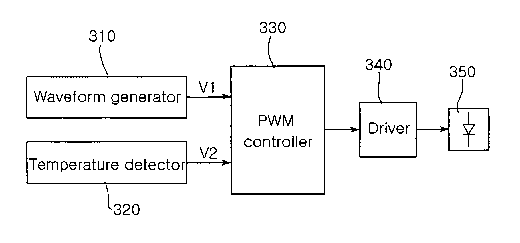
[0041]FIG. 3 is a circuit diagram for controlling a light emitting diode (LED) according to the invention.

[0042]Referring to FIG. 3, the circuit for controlling the LED includes a waveform generator 310, a temperature detector 320, a PWM controller 330 and a driver 340. The waveform generator 310 generates a sawtooth wave V1 for Pulse Width Modulation (PWM) control. The temperature detector 320 detects a voltage V2 via a resistance value which is linearly variable according to changes in an ambient temperature. The PWM controller 330 compares the sawtooth wave V1 from the wave generator with the detection voltage V2 from the temperature detector and generates a PWM voltage Vpwm having a duty determined by the comparison result. The d...


PUM


Abstract

A circuit for controlling an LED with temperature compensation is employed in the LED-based system. The circuit of the invention linearly controls luminance and color of the LED according to temperature change and more precisely compensates for temperature-related variations in LED properties. Also, the circuit saves the cost of the product due to no requirement of a microprocessor. In the circuit, a waveform generator generates a sawtooth wave for Pulse Width Modulation (PWM) control. A temperature detector detects a voltage via a resistance value which is linearly variable according to changes in an ambient temperature. A PWM controller compares the sawtooth wave from the wave generator with the detection voltage from the temperature detector and generates a PWM voltage having a duty determined by the comparison result.

Description

CLAIM OF PRIORITY[0001]This application claims the benefit of Korean Patent Application No. 2005-84312 filed on Sep. 9, 2005 in the Korean Intellectual Property Office, the disclosure of which is incorporated herein by reference.BACKGROUND OF THE INVENTION[0002]1. Field of the Invention[0003]The present invention relates to a circuit for controlling a Light Emitting Diode (LED) which is employed in a backlight system or a lighting system. More particularly, the present invention relates to a circuit for controlling an LED which can linearly control luminance and color according to changes in an ambient temperature to more precisely compensate for temperature-induced variations in LED properties, and save the cost of the product due to no requirement of a microprocessor.[0004]2. Description of the Related Art[0005]In general, a Cold Cathode Fluorescent Lamp (CCFL) is largely employed in a Liquid Crystal Display (LCD) and other back light systems for electronic display. However, attem...

Claims


Application Information

Patent Timeline
Patent Type & Authority Patents(United States)
IPC IPC(8): G05F1/00H01L33/00H05B37/02
CPCG09G3/3406G09G2310/06G09G2320/041G09G2320/043G09G2320/064G02F1/133
Inventor JOUNG, IL KWEON
Owner SAMSUNG ELECTRONICS CO LTD
Why Eureka
Try Eureka