Combustion chamber for a gas turbine

a gas turbine and combustion chamber technology, applied in the direction of machines/engines, burner noise abatement, light and heating equipment, etc., can solve the problems of insufficient degree of accuracy of inability to accurately predict new combustion chamber oscillations, and difficulty in adjusting dampers or entire dampers, etc., to achieve the effect of simplifying the frequency adaptation

Inactive Publication Date: 2008-02-19
ANSALDO ENERGIA IP UK LTD
View PDF17 Cites 27 Cited by
  • Summary
  • Abstract
  • Description
  • Claims
  • Application Information

AI Technical Summary

Benefits of technology

[0008]Accordingly, the invention relates to providing a combustion chamber for a gas turbine with a Helmholtz damper that avoids the drawbacks of known combustion chambers and in particular is distinguished by greatly simplified adaptation to the frequencies that are to be damped.
[0009]The Helmholtz damper is to be designed in such a manner that its damping frequency is adjustable, in particular continuously adjustable. This makes it easy to match the damping to the thermoacoustic characteristics of the combustion chamber, so that it can be optimized accordingly. There is no need to replace parts or entire dampers, and consequently there is no need for correspondingly large access features. At the same time, the adjustability of the Helmholtz dampers eliminates the need to produce and keep available damper parts or dampers of different configuration for different resonant frequencies.
[0010]One preferred configuration of the invention is distinguished by the fact that the damping volume of the Helmholtz damper is continuously variable. This type of adjustability for the damping frequency can be realized in a particularly simple and effective way.
[0012]It is preferable for the variability of the volume to be achieved by virtue of the variable damping volume being delimited on one side by a displaceable piston. This configuration is in mechanical terms very simple to realize and is functionally reliable and simple to actuate in operation.
[0014]Since the combustion chamber is arranged inside a turbine casing, it is particularly advantageous for actuation of the Helmholtz damper if the adjustment element can be actuated through a closeable access opening in the turbine casing. The adjustment element may in this case easily be designed in such a way that only a small opening, which requires only insignificant changes to the turbine casing, is required for its actuation.

Problems solved by technology

Since the frequency and amplitude of the thermoacoustic oscillations that occur in a combustion chamber are influenced by a very wide range of geometric and operational parameters of the combustion chamber, the likely oscillations in a new combustion chamber cannot be predicted with anything like a sufficient degree of accuracy.
It may therefore be the case that the Helmholtz dampers used at the combustion chamber are not optimally matched to the oscillations that actually occur in the combustion chamber.
Drawbacks in this context are firstly that matching to a resonant frequency can only take place in stages, that it is very difficult to exchange parts of dampers or entire dampers, and that a considerable design outlay is required at the turbine casing and the combustion chamber for this exchange to be performed.

Method used


Image

  • Combustion chamber for a gas turbine
  • Combustion chamber for a gas turbine

Examples


Embodiment Construction

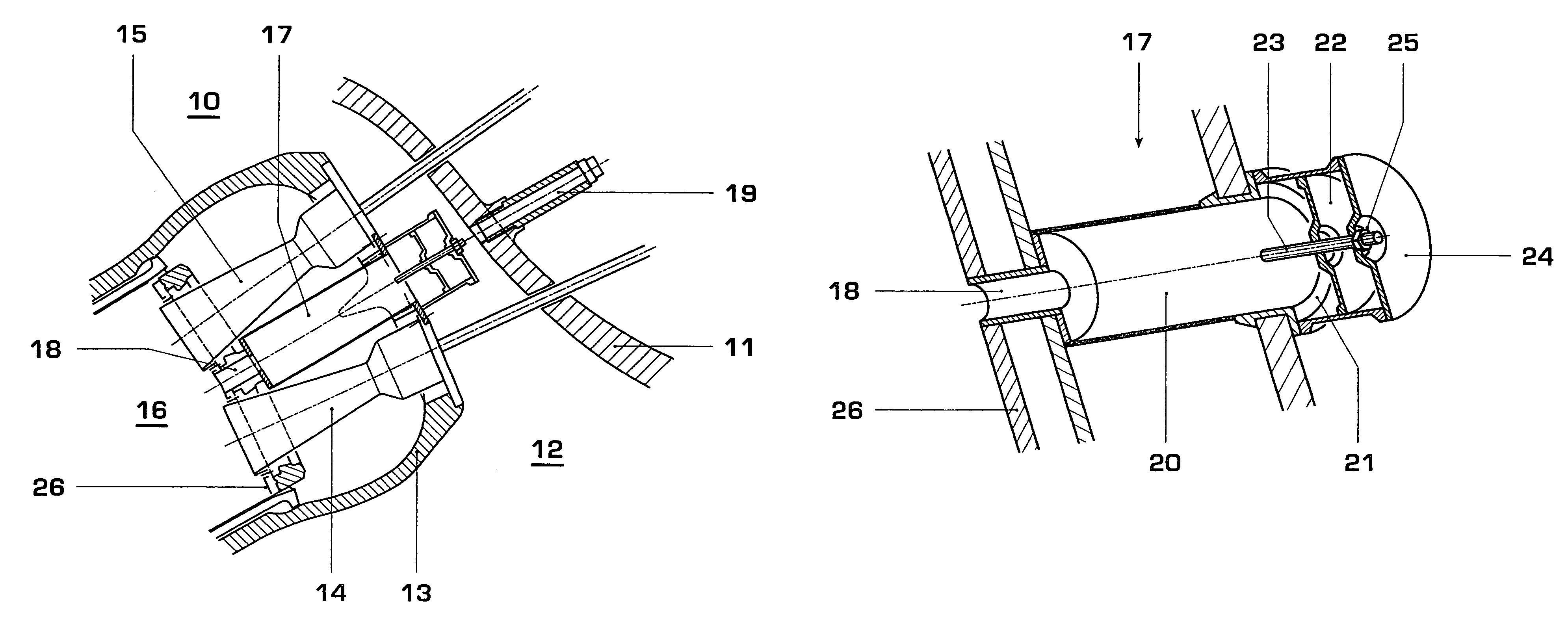
[0019]FIG. 1 shows an excerpt from a cross-section through the entry side of the combustion chamber of a gas turbine with two rings of double-cone burners and adjustable Helmholtz dampers arranged therebetween, in accordance with a preferred exemplary embodiment of the invention. The gas turbine 10 is surrounded by a gas turbine casing 11, inside which there is a plenum 12 filled with compressed air. The plenum 12 surrounds the combustion chamber 16, which is separated from the plenum 12 by a combustion-chamber casing 13. The arrangement of the combustion chamber 16 within the gas turbine 10 is substantially the same as that described in EP A1 0 597 138, which was cited in the introduction. On the entry side, the combustion chamber 16 is delimited within the combustion-chamber casing 13 by a front cover 26. The combustion chamber 16 is annular in design and is fitted with burners 14, 15 that are configured in a known way as double-cone burners and are arranged in rings around the ax...


PUM


Abstract

At least one Helmholtz damper is arranged at a combustion chamber for a gas turbine in order to damp thermoacoustic oscillations; the damping volume of this Helmholtz damper is in communication with the combustion chamber via a connecting passage. Optimum damping is achieved in a simple way by virtue of the Helmholtz damper being designed in such a manner that its damping frequency is adjustable.

Description

CROSS-REFERENCE TO RELATED APPLICATIONS[0001]This application is a continuation of the U.S. National Stage designation of co-pending International Patent Application PCT / CH02 / 00696 filed Dec. 16, 2002, the entire content of which is expressly incorporated herein by reference thereto.FIELD OF THE INVENTION[0002]The present invention deals with the field of gas turbine engineering. It relates to a combustion chamber for a gas turbine.BACKGROUND OF THE INVENTION[0003]A combustion chamber is known, for example, from EP A1 0 597 138 and U.S. Pat. No. 5,373,695.[0004]As is explained in the introduction to the above documents, the problem of thermoacoustic oscillations is becoming increasingly significant in modern low-NOx combustion chambers of gas turbines. Therefore, the prior art has given various proposals for arranging what are known as Helmholtz dampers at the combustion chamber of a gas turbine; the configuration of these dampers, in which a damping volume is in communication with ...

Claims


Application Information

Patent Timeline
Patent Type & Authority Patents(United States)
IPC IPC(8): F02C7/24F23R3/00F23M20/00
CPCF23M20/005F23R3/002F05B2260/96F23D2210/00F23R2900/00013F23R2900/00014
Inventor GRAF, PETERTSCHIRREN, STEFANWUNDERLE, HELMAR
Owner ANSALDO ENERGIA IP UK LTD
Why Eureka
Try Eureka