Temperature measuring method using micro temperature sensing element

a temperature sensing element and temperature measurement technology, applied in heat measurement, instruments, nanostructure manufacturing, etc., can solve the problems of inability to know the temperature of the subject at high temperature, the length of the columnar gallium as the temperature sensing element cannot be read,

Inactive Publication Date: 2008-02-19
NAT INST FOR MATERIALS SCI
View PDF6 Cites 11 Cited by
  • Summary
  • Abstract
  • Description
  • Claims
  • Application Information

AI Technical Summary

Problems solved by technology

However, as to the temperature measuring method, utilizing a nano thermometer utilizing a gallium column discussed above, the length of the columnar gallium as the temperature sensing element cannot be read unless the subject to be measured is introduced into the observation area of the high resolution transmission type electron microscope.
On the other hand, once the temperature sensing element removed from the inside of the subject to the outside for the temperature measurement, since the length of the columnar gallium returns to the length at room temperature, an accurate temperature of the subject at the high temperature cannot be known.

Method used


Image

  • Temperature measuring method using micro temperature sensing element
  • Temperature measuring method using micro temperature sensing element
  • Temperature measuring method using micro temperature sensing element

Examples


example 1

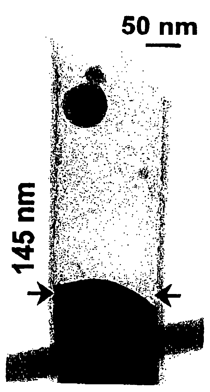
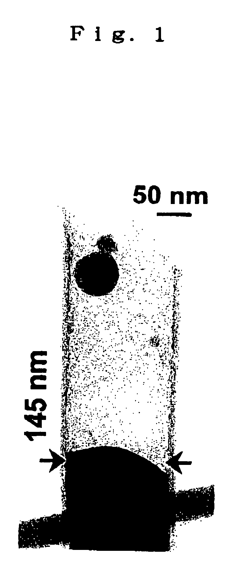
[0029]A temperature sensing element was produced according to the method disclosed in the above-mentioned document 3. The structure thereof was confirmed by a high resolution transmission electron microscopy with an X-ray energy diffusion spectrometer mounted. The temperature sensing element was applied onto a grid for the observation by the high resolution transmission electron microscopy. Then, the temperature sensing element was observed by the high resolution transmission electron microscopy was maintained at 20° C. and 58° C. for measuring the height of the gallium.

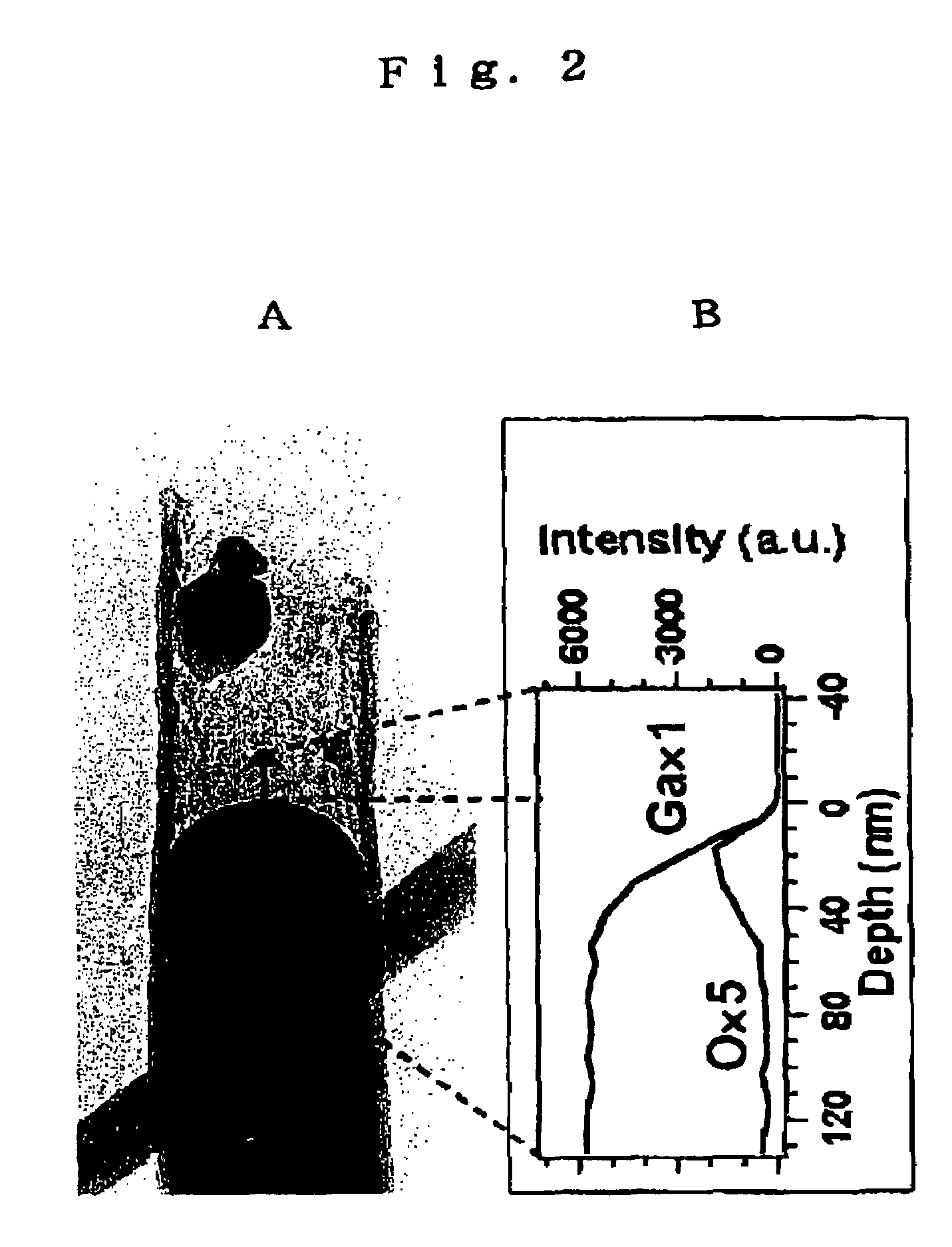
[0030]FIG. 1 is a high resolution transmission electron microscope image showing the height of the gallium at the time of observing the temperature sensing element at 20° C. FIG. 2(A) is an image of the temperature sensing element observed again at 20° C. using the high resolution transmission electron microscope after introducing the same into a furnace in the air, heating at 358° C. and removal. As shown in FIG. 2(...

example 2

[0033]FIG. 3 is an image of the same temperature sensing element as in Example 1 observed using the high resolution transmission electron microscope after heating to 440° C. FIG. 4 is an image thereof observed at 20° C. using the same high resolution transmission electron microscope after heating and removal.

[0034]From FIG. 4, since the gallium oxide layer is bonded firmly with the inner wall of the carbon nano tube, the gallium oxide thin layer position is not changed even after the temperature drop.

[0035]It is confirmed that gallium layer (1) of a low density layer is formed in the lower part of the gallium layer, and that the gallium oxide layer is bonded firmly with the inner wall of the carbon nano tube.

[0036]As a result of the measurement using the high resolution transmission type electron microscope accordingly, the height difference of the gallium top ends in FIG. 1 and FIG. 2(A) was 170 nm. According to the calculation using the numerical values, the gallium volume V0 init...


PUM

PropertyMeasurementUnit
diameteraaaaaaaaaa
lengthaaaaaaaaaa
temperatureaaaaaaaaaa

Abstract

By preliminarily measuring the gallium temperature and the length change of a temperature sensing element comprising a carbon nanotube having a continuous column of gallium contained therein, then heating the temperature sensing element installed in a subject to increase the temperature thereof in air, removing the temperature sensing element subjecting to measure the gallium length, and substituting the measured gallium length in a formula, the temperature is measured accurately over a wide temperature range in a micrometer size or less environment.

Description

TECHNICAL FIELD[0001]The present invention relates to a temperature measuring method using a minute size temperature sensing element. More specifically, it relates to a novel temperature measuring method capable of measuring the temperature accurately over a wide range, using a temperature sensing element comprising a carbon nanotube containing columnar gallium.BACKGROUND ART[0002]After the discovery of the carbon nanotube in 1991, a number of studies have been carried out by many researchers. Various technical improvements and methods of utilization have been discovered concerning carbon nanotubes. For example, nowadays, it is utilized widely for field effect devices, probe top ends for scanning probe microscopes, superconductive materials, highly sensitive microbalances, structural materials, minute forceps for the nanoscale operation, parts for gas detectors, hydrogen energy storage devices, or the like. Moreover, studies have been executed actively for containing the various fil...

Claims


Application Information

Patent Timeline
Patent Type & Authority Patents(United States)
IPC IPC(8): G01K5/00B82B3/00G01K5/02G01K5/10
CPCB82Y30/00G01K5/02G01K5/10G01K2211/00Y10S977/744Y10S977/955
Inventor BANDO, YOSHIOGAO, YIHUALIU, ZONGWENGOLBERG, DMITRI
Owner NAT INST FOR MATERIALS SCI
Why Eureka
Try Eureka