
Doctor bed

a doctor bed and bed frame technology, applied in the field of doctor beds, can solve the problems of high fit, high wear of the doctor bed, and high wear of the doctor bed, and achieve the effects of high wear resistance, high quality, and high wear resistan

Inactive Publication Date: 2008-02-19
VOITH PATENT GMBH
View PDF5 Cites 3 Cited by
  • Summary
  • Abstract
  • Description
  • Claims
  • Application Information

AI Technical Summary

Benefits of technology

The present invention provides a doctor bed for a machine processing a moving material web, which includes a housing with a cross section at right angles to the cylinder longitudinal axis of the metering rod and a wiping strip that can be detachably arranged between the metering rod and the doctor bed. The wiping strip is designed to improve the period of use of the doctor bed and the quality of the coating to be applied with the aid of the doctor bed. The wiping strip can be easily installed and maintained, and it can be replaced independently of the other parts of the doctor bed. The wiping strip is designed to ensure high-quality wiping of the coating material off the metering rod and uniformity of the application thickness of the coating material. The wiping strip can be produced from a material that is more resistant to wear and damage than the material of the metering rod. The doctor bed and the metering rod can be spaced apart in the direction of rotation of the metering rod to ensure even distribution of the coating material. The wiping strip can be resiliently pressed against the metering rod to ensure constant and high-quality wiping. The wiping strip can be made of a material that can be deformed elastically, such as rubber and graphite, or a dimensionally stable, abrasion-resistant material, such as plastic or ceramic. The wiping strip can touch the metering rod along one line or it can taper to a point comparable with a doctor blade on its side facing the metering rod.

Problems solved by technology

Because of the dual function of the doctor bed, firstly the mounting of the metering rod and secondly its permanent cleaning, its period of use is highly restricted.
A disadvantage of this approach is that the press fit needs a high amount of drive power from the motor to drive the metering rod and there is rapid wear of the doctor bed.
The disadvantages with this doctor bed include firstly, the many individual parts of the housing cause its construction to be complicated, which entails the risk of faulty installation during assembly and reduced operational reliability because of the detachable connections between the individual parts of the housing.
Secondly, the fine adjustment of the mounting of the metering rod, by way of screws, cause there to be a great deal of effort when adjusting the doctor bed during installation, servicing and maintenance of a machine for processing a moving material web.
Additionally, there is the risk of an inaccurate setting of the mounting of the metering rod, causing stresses, and the loosening of the setting during operation.
A stoppage of the machine caused by adjustment work results in enormous costs, since production has to be stopped for this purpose.

Method used


Image

  • Doctor bed
  • Doctor bed
  • Doctor bed

Examples


Embodiment Construction

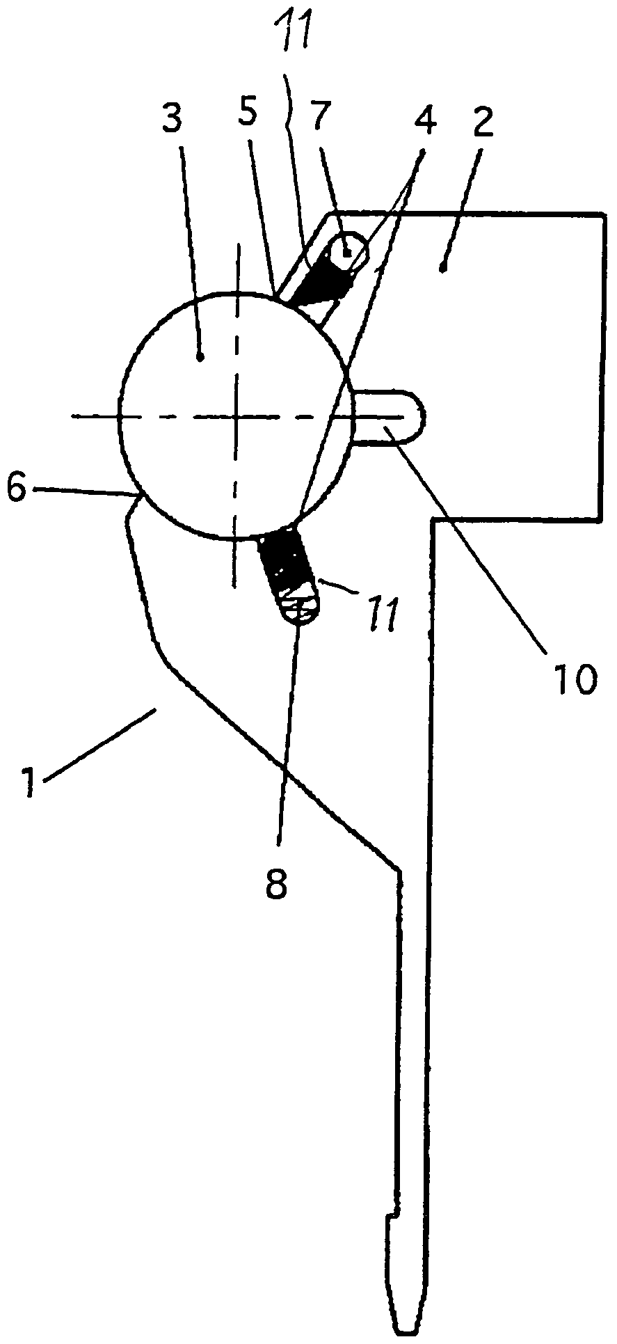
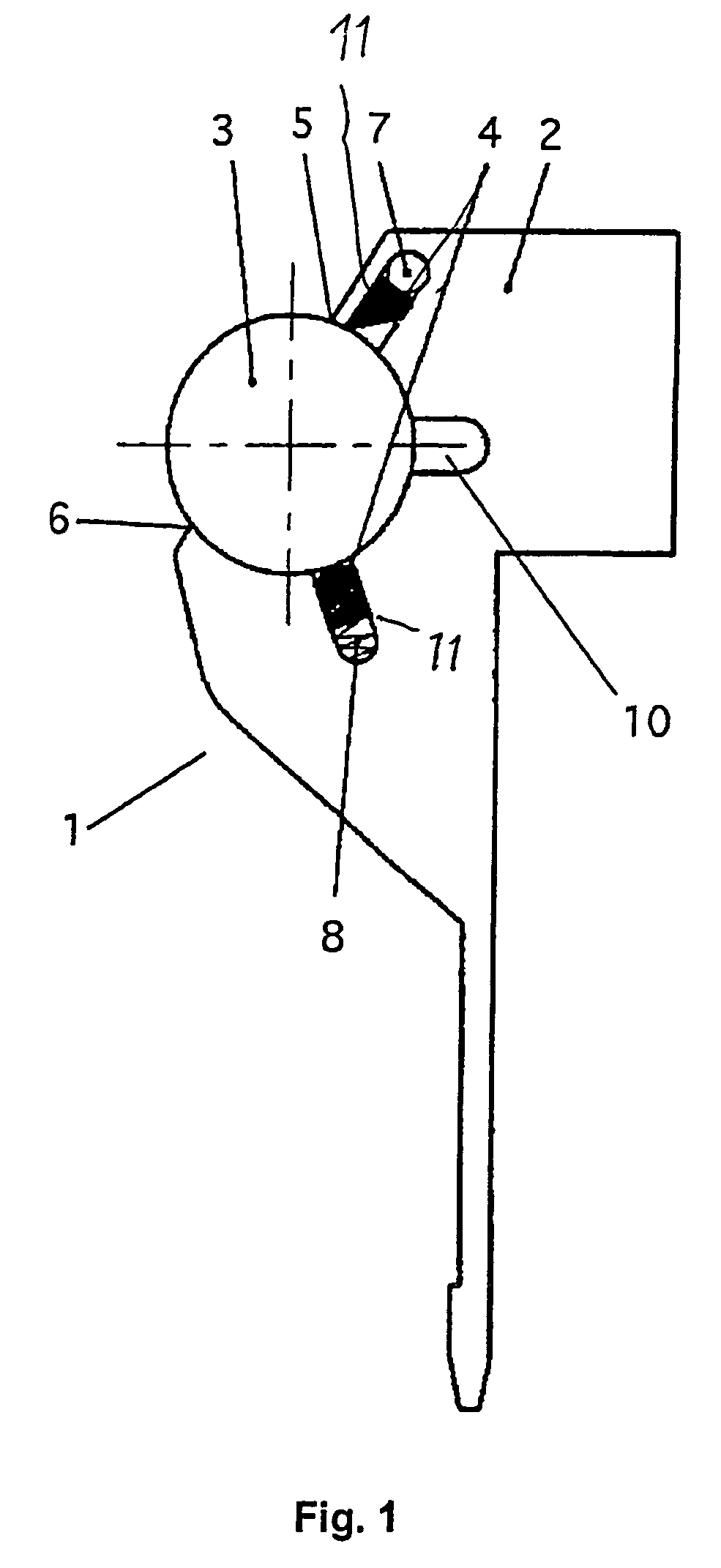
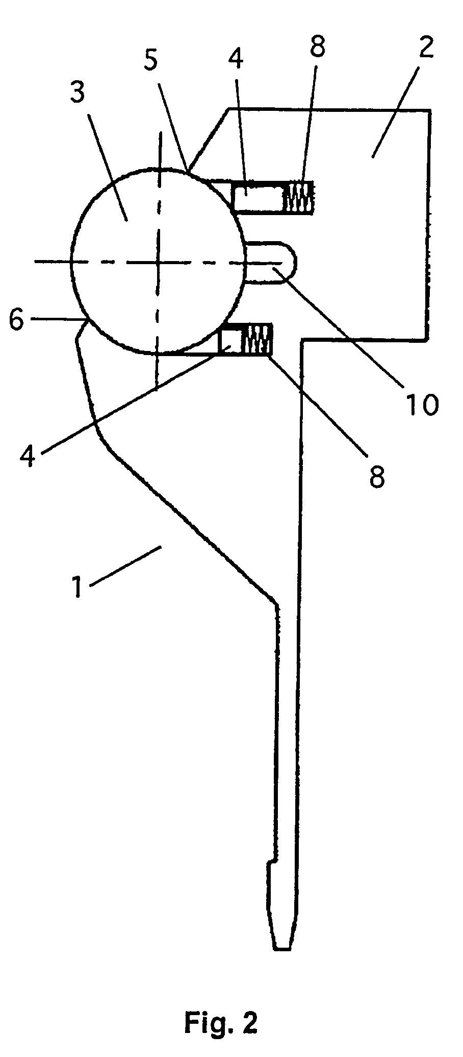
[0029]A doctor bed 1 illustrated in FIGS. 1 and 2 include a housing 2, which has a circularly cylindrical recess for holding a circularly cylindrical metering rod 3. The recess encloses metering rod 3 by more than 180°, part of the periphery of metering rod 3 remaining exposed. Housing 2 is produced in one piece from a homogenous material, in the cross section it is illustrated as running at right angles to the cylinder longitudinal axis of metering rod 3. In order to reliably wipe off the coating material, that is to be distributed uniformly over the width of a moving material web, not illustrated, by metering rod 3 in housing 2, wiping strips 4 are arranged in grooves 11 running parallel to the cylinder longitudinal axis of metering rod 3. In FIG. 1, a wiping strip 4 is arranged directly at an entry edge 5 of doctor bed 1, a second wiping strip 4 is arranged at an angle to first wiping strip 4, and is arranged downstream in the direction of rotation of a washing channel 10 arrange...


PUM

PropertyMeasurementUnit
lengthaaaaaaaaaa
rotationaaaaaaaaaa
compressive stressaaaaaaaaaa

Abstract

A doctor bed is provided for holding a circularly cylindrical metering rod, including a housing of a homogenous material, which is designed with a cross section at right angles to the cylinder longitudinal axis of the metering rod and has a circularly cylindrical recess which surrounds the metering rod with a form fit over at least 180°. The doctor bed is arranged on a machine processing a moving material web, there being arranged on the housing, in the region of the recess, at least one groove running parallel to the cylinder longitudinal axis of the metering rod. A wiping strip is arranged detachably between the metering rod and the doctor bed.

Description

BACKGROUND OF THE INVENTION[0001]1. Field of the Invention[0002]The present invention relates to a doctor bed for holding a circularly cylindrical metering rod.[0003]2. Description of the Related Art.[0004]A known process for finishing material webs, in particular of paper, board, film or combinations of these materials, provides for the application of a liquid or pasty coating material, directly or indirectly via a transfer element, for example a roll, to the material web on a machine processing a moving material web. The coating material has to be metered and / or distributed uniformly onto the material web (brought to the desired coat weight) over the width of the latter or the transfer element. A very good quality of such finishing is achieved if the metering and / or distribution of the coating material is carried out by way of a circularly cylindrical metering rod rotating counter to the running direction of the material web or the transfer element to which the coating material is...

Claims


Application Information

Patent Timeline
Patent Type & Authority Patents(United States)
IPC IPC(8): B05C1/08B05C11/02D21H25/12
CPCB05C11/025D21H25/12B05C1/0817
Inventor HENNINGER, CHRISTOPHKAIPF, HORSTSCHAUBMAIER, MARTINHEITZINGER, MICHAELKEINBERGER, RUEDIGER
Owner VOITH PATENT GMBH
Learn More