
Ride-through method and system for HVAC&R chillers

a chiller and ride-through technology, applied in the field of variable speed drives, can solve the problems of dc link voltage to sag, voltage sag, vsds are particularly susceptible to undervoltage conditions, etc., to prevent the chiller system from shutting down, reduce the discharge of dc link capacitors, and improve the ride-through capability of input voltage sag

Active Publication Date: 2008-02-19
JOHNSON CONTROLS TYCO IP HLDG LLP +1
View PDF35 Cites 40 Cited by
  • Summary
  • Abstract
  • Description
  • Claims
  • Application Information

AI Technical Summary

Benefits of technology

This solution enhances the ride-through capability of VSDs during voltage sags by minimizing DC link capacitor discharge, utilizing the energy stored in the motor and compressor inertia, and leveraging thermal storage in refrigerant and chilled water systems to maximize system operational time.

Problems solved by technology

VSDs are particularly susceptible to undervoltage conditions, referred to as voltage sags, occurring on the utility supply input.
Such voltage sags may cause the DC link voltage to sag, and the VSD system to shut down.
A passive rectifier therefore does not compensate for the variations in input line voltage.
Consequently, a voltage sag will cause the DC link voltage to drop, which, in turn, may cause the VSD to shutdown.
All of these require additional hardware and therefore significantly increase the cost of a VSD.
This method typically requires motor speed and current sensors, which may add to the cost of a VSD.
Due to the practical current conduction and current switching limitations of the boost rectifier components, the input AC current cannot be allowed to increase indefinitely.
However, if the line voltage continues to drop after the current limit of the boost rectifier is reached, the boost rectifier is no longer capable of regulating the output DC voltage to the setpoint value although the input current remains controlled at the current limit level.

Method used


Image

  • Ride-through method and system for HVAC&R chillers
  • Ride-through method and system for HVAC&R chillers
  • Ride-through method and system for HVAC&R chillers

Examples


Embodiment Construction

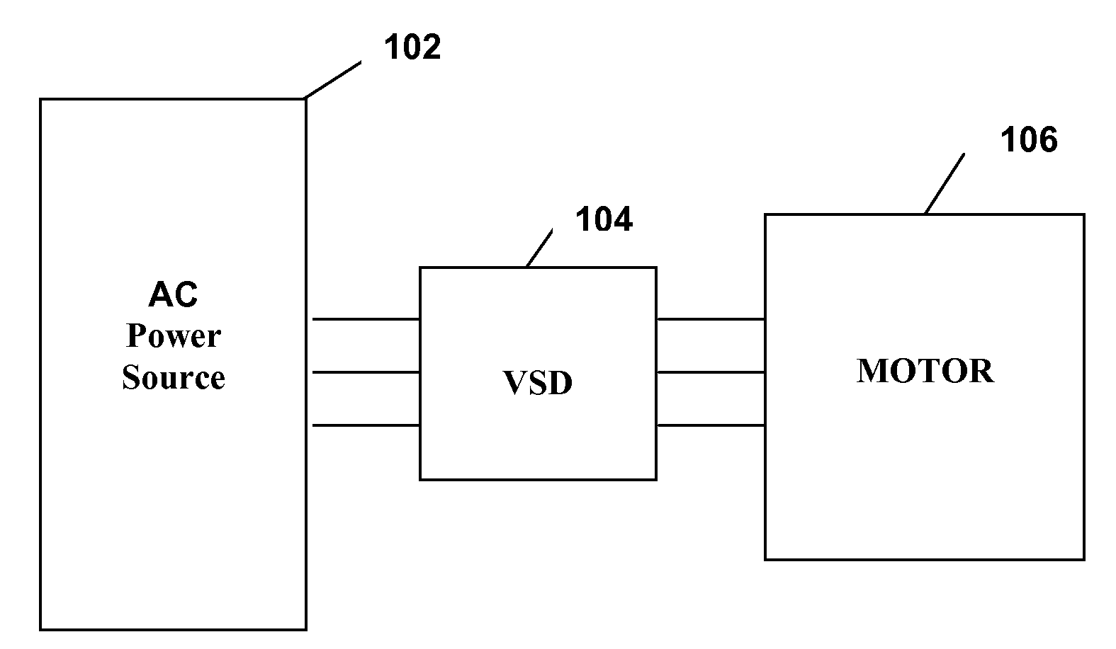
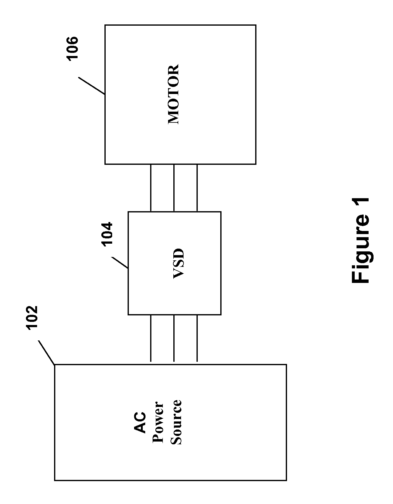
[0026]FIG. 1 illustrates generally the system configuration of the present invention. An AC power source 102 supplies fixed voltage and frequency AC power to a variable speed drive (VSD) 104, which in turn, supplies variable voltage and frequency AC power to a motor 106. The motor 106 is preferably used to drive a corresponding compressor of a refrigeration or chiller system (see generally, FIG. 3). The AC power source 102 provides single phase or multi-phase (e.g., three phase), fixed voltage, and fixed frequency AC power to the VSD 104 from an AC power grid or distribution system that is present at a site. The AC power grid can be supplied directly from an electric utility or can be supplied from one or more transforming substations between the electric utility and the AC power grid. The AC power source 102 can preferably supply a three phase AC voltage or line voltage of 200 V, 230 V, 380 V, 460 V, or 575 V, at a line frequency of 50 Hz or 60 Hz to the VSD 104 depending on the co...


PUM


Abstract

A method of providing ride-through capability in a chiller / refrigeration system employs a variable speed drive with an active converter stage, a DC link stage and an inverter stage for providing variable frequency and voltage to power at least one motor. An induction motor is coupled to the output of the inverter stage for driving a compressor in the chiller / refrigeration system. The ride-through method comprises operating the active converter to regulate the DC link voltage of the DC link stage to a predetermined voltage level until the current through the active converter equals a predetermined current limit, then transferring regulation of the DC link to the inverter upon reaching the current limit of the converter. The compressor is unloaded, and the power flow through the inverter is reversed to maintain the voltage level of the DC link stage. Pre-rotation vanes, slide valve, or check valve are used to unload the compressor.

Description

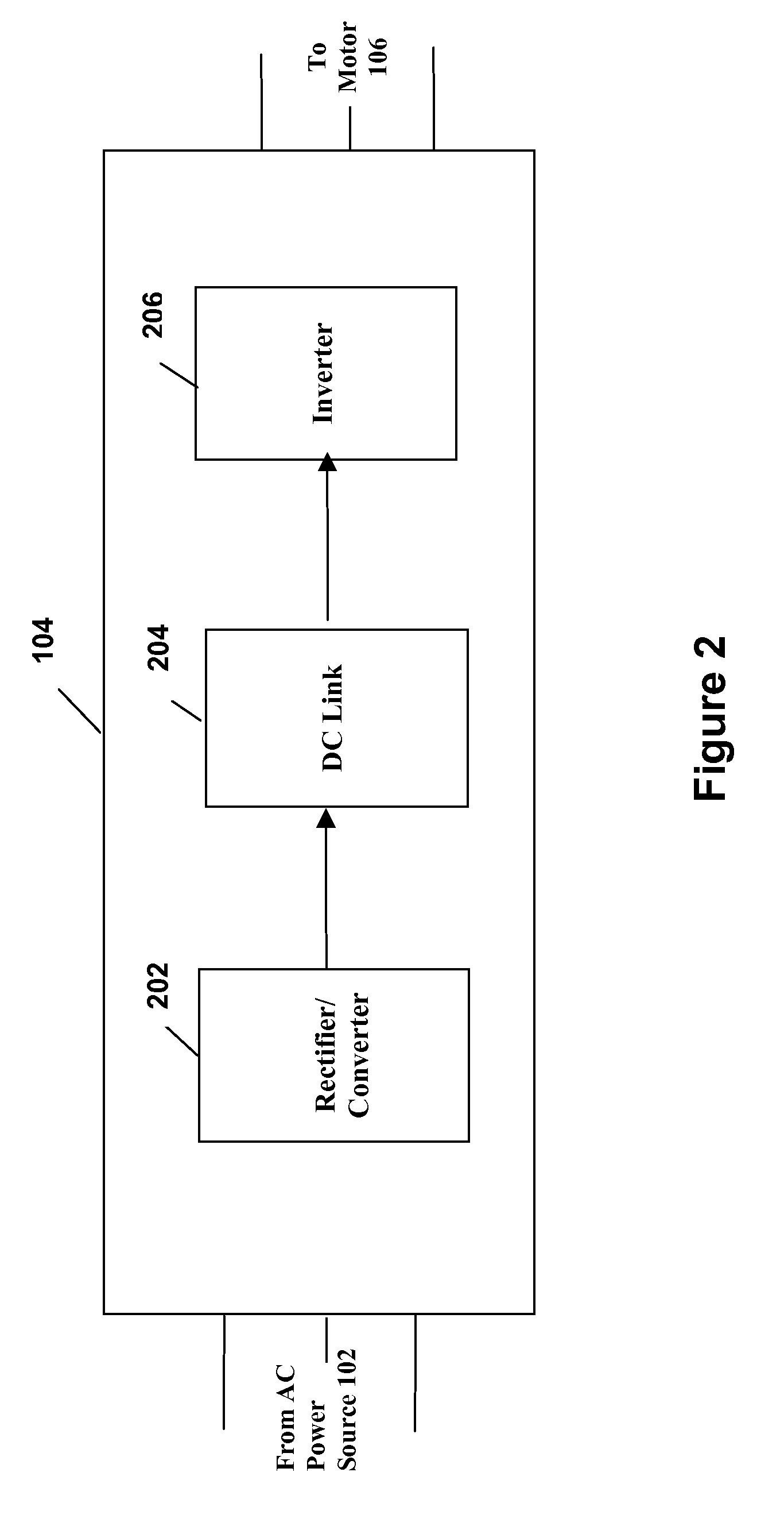
CROSS-REFERENCES TO RELATED APPLICATIONS[0001]This application is a continuation-in-part of application Ser. No. 11 / 218,757, filed Sep. 2, 2005 now U.S. Pat. No. 7,081,734.BACKGROUND OF THE INVENTION[0002]The present invention relates generally to variable speed drives, and more specifically, to variable speed drives with voltage-sag ride through capability for use in heating, ventilation, air conditioning and refrigeration (HVAC&R) equipment.[0003]Variable speed drives (VSDs) are used in HVAC&R systems to provide variable magnitude and variable frequency AC voltage to motors driving refrigeration compressors. VSDs are typically comprised of an input rectifier, a DC link and an inverter. Line AC voltage, supplied at a fixed magnitude and fixed frequency by an electric utility, is rectified by the VSDs input rectifier into a DC voltage. This DC voltage is filtered and stabilized by the passive components with energy storage capability (such as capacitors) at the DC link. The DC link ...

Claims


Application Information

Patent Timeline
Patent Type & Authority Patents(United States)
IPC IPC(8): H01R39/46H02K13/00H02P25/12
CPCH02J9/062H02M5/458H02P27/04
Inventor SCHNETZKA, HAROLD R.JADRIC, IVAN
Owner JOHNSON CONTROLS TYCO IP HLDG LLP
Learn More