Photometric analysis

a technology of liquid photometry and meter, applied in the direction of material analysis, instruments, withdrawing sample devices, etc., can solve the problems of meter not being useful for photometric analysis, introducing errors into the test, and optical mismatch between cuvettes

Active Publication Date: 2008-02-19
IND TEST SYST
View PDF6 Cites 14 Cited by
  • Summary
  • Abstract
  • Description
  • Claims
  • Application Information

AI Technical Summary

Benefits of technology

[0015]In accordance with the second inventive aspect, the sample is beneficially added to the photometric cell or photometric instrument well, by immersing a portion of the photometric cell or photometric instrument well in a bulk volume of an aqueous liquid to be analyzed, such as swimming pool or spa water, and thereafter withdrawing the photometric cell or photometric instrument well from the aqueous liquid. Advantageously, in accordance with the second inventive aspect, the photometric instrument is a waterproof photometric instrument. By the term “waterproof” is meant, for purposes of this description, impervious to water, and is to be distinguished from water-resistant. The imperviousness of a waterproof photometric instrument beneficially protects function-critical instrument components, including but not limited to, electronic and power components, from contact with water. The photometric instrument well of a particularly beneficial waterproof photometric instrument, is located near an end of the photometric instrument.

Problems solved by technology

It is recognized that nicks and scratches from handling may cause an optical mismatch between cuvettes and introduce error into the test results.
It is recognized that because cuvette orientation in a photometric instrument will greatly affect test results, a cuvette should always be inserted into the instrument so that the cuvette has the same orientation to the light path, and that variability in the geometry and quality of the glassware can cause variability in results.
The meter is not useful for photometric analysis.

Method used


Image

  • Photometric analysis
  • Photometric analysis
  • Photometric analysis

Examples


example 1

Free Chlorine & Total Chlorine

[0087]Chlorine analysis has wide commercial applicability, and is useful for testing drinking water, pool and spa water, aquarium water, industrial and environmental water, and for other types of water testing. Medical applicability includes testing of equipment such as dialysis equipment to confirm removal of chlorine and chloramine contaminants. Furthermore, chlorine analysis has applications to food processing. Chlorine can be present in water as free available chlorine and as combined available chlorine. Both forms can be determined together as total available chlorine.

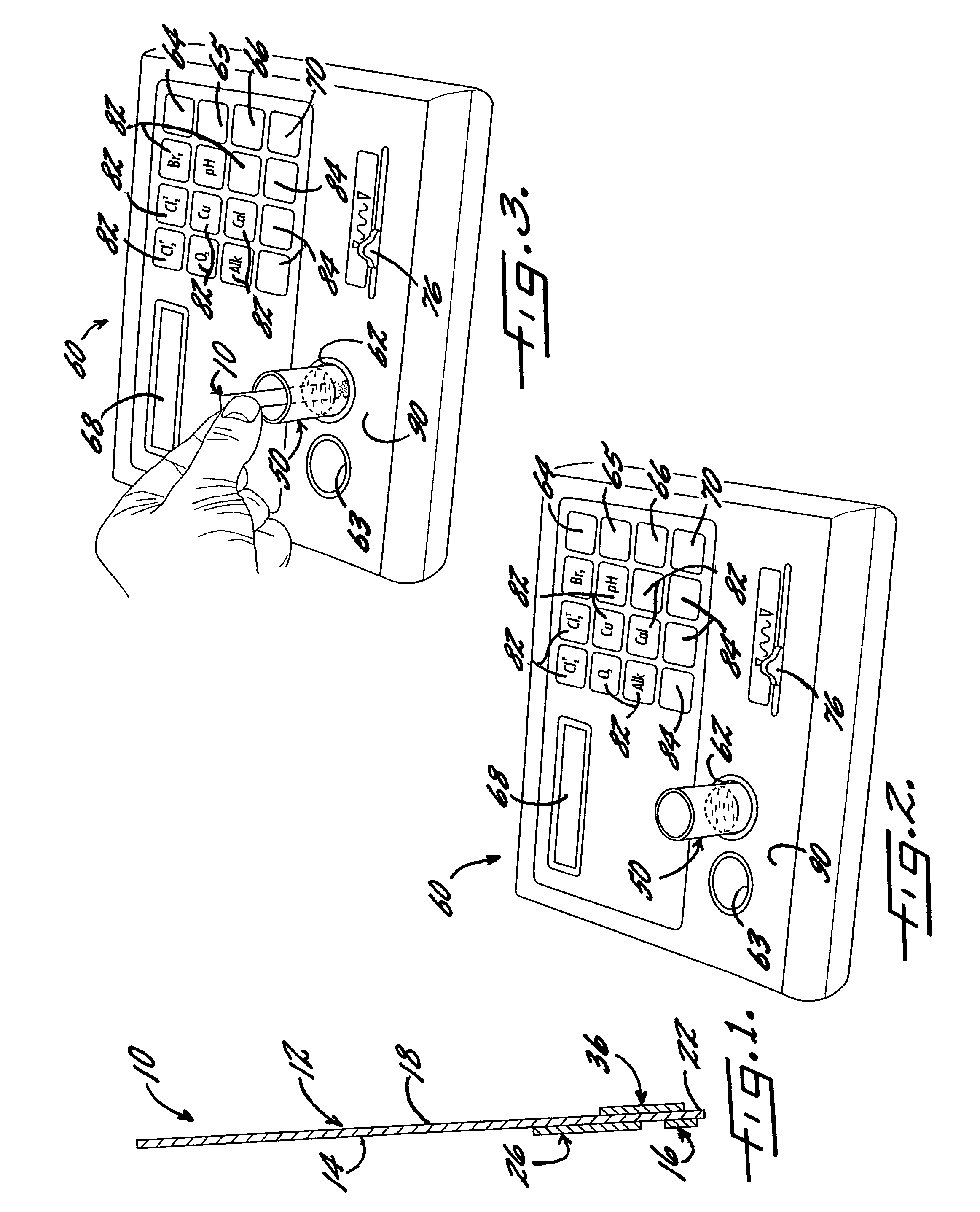
[0088]With reference again to reagent delivery device 10 of FIG. 1, in a convenient embodiment, support 12 is made of PVC, is 8 mm wide and has a thickness of 0.009 inches, carrier 16 is ¼″ long and 8 mm wide, and carriers 26,36 are each ½″ long and 8 mm wide. The carriers are fibrous pads made of Schleicher and Schuell 497 paper, which has a thickness of about 0.2 mm.

[0089]¼″ long ca...

example 2

Scratched Photometric Cells

[0101]This Example demonstrates that the inventive photometric technology beneficially substantially eliminates variations in data resulting from optical variability of photometric cells.

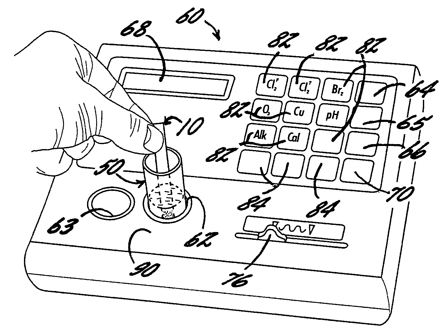
[0102]With reference to FIGS. 2 and 3, a multiwavelength photometer 60 is shown. Conveniently, photometer 60 is an Palintest Pooltest 9 photometer. Photometric instrument 60 beneficially includes a cell chamber 62 for receiving a photometric cell 50 for optical analysis, an ON touch pad 64, an OFF touch pad 65, a display 68, a touch pad 70 for zeroing the instrument and for display of optical readings, and a slide switch 76 for selecting a 520 nm or 570 nm wavelength. A photometric cell holding chamber 63 is not needed in the inventive methodology. A touch pad 66 when used to activate the SYSTEM mode, beneficially allows system options such as displaying mg / L or ppm.

[0103]Photometric instrument 60 also beneficially includes a plurality of touch pads 82 each for selecting a...

example 3

Waterproof Photometer

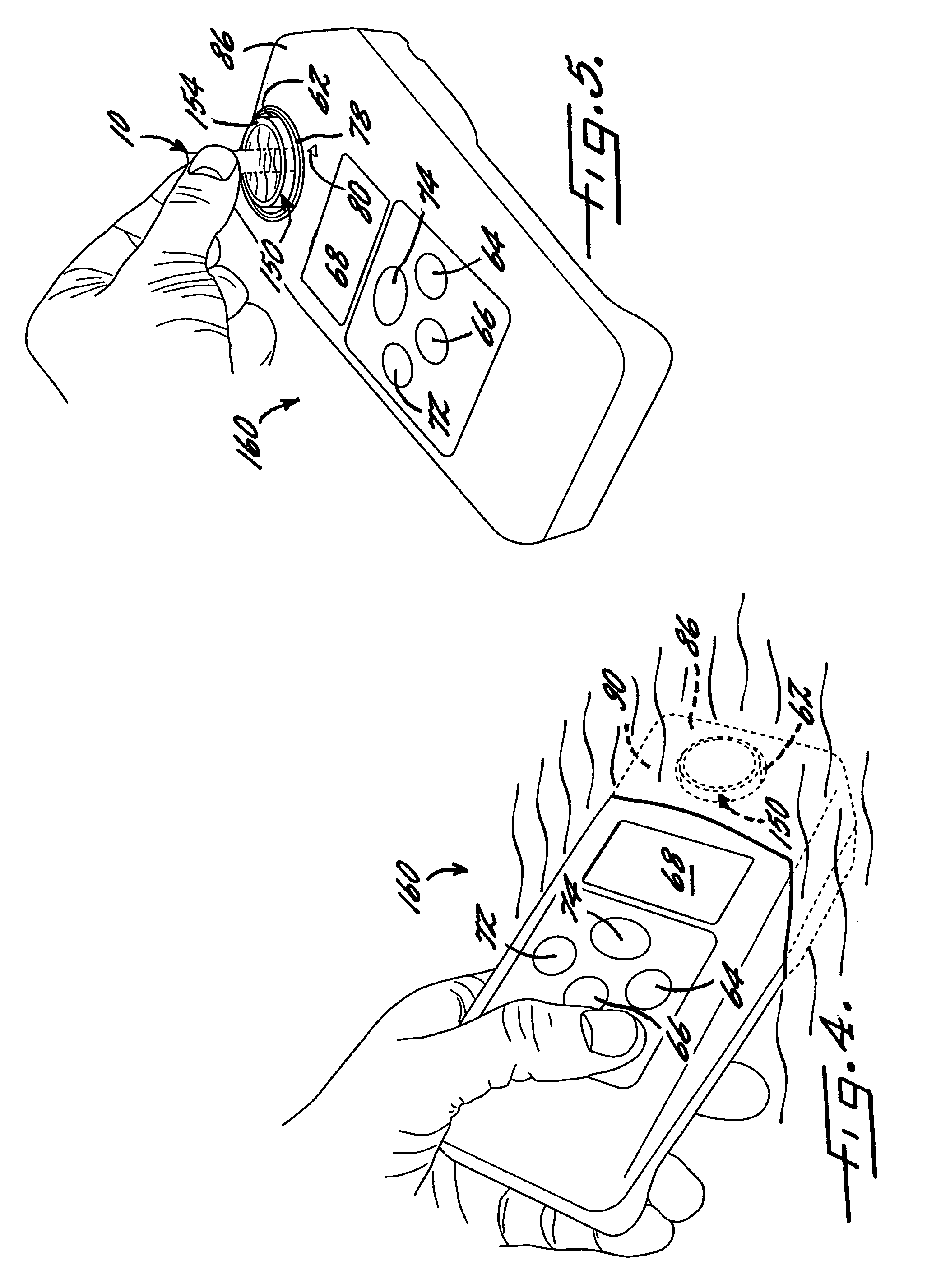
[0112]With reference to FIGS. 4 and 5, a waterproof photometer 160 is shown. Conveniently, photometer 160 is an Oakton Colorimeter C201. The photometric instrument includes power button 64, mode touch pad 66, display 68, a touch pad 72 for zeroing the photometer, and a touch pad 74 for entry of the selected mode and display of optical readings. The C201 instrument provides for analysis of free chlorine and total chlorine, using a wavelength of 525 nm. The analysis desired is selected using mode touch pad 66 to select an appropriate algorithm. Beneficially for the inventive methodology of this Example, cell chamber 62 of the C201 instrument is located near an end 86 of the instrument. The C201 instrument further includes optical window alignment mark 80.

[0113]An appropriately dimensioned plastic photometric cell 150 is friction fit in cell chamber 62 of waterproof photometer 160, and, without interfering with the optical window of the cell chamber, sealed in the ...


PUM

PropertyMeasurementUnit
optical path lengthaaaaaaaaaa
thicknessaaaaaaaaaa
volumeaaaaaaaaaa

Abstract

A beneficial photometric analytical method is described according to which an effective amount of at least one analytical agent for photometric analysis, is delivered from a support into a liquid sample, and advantageously a mixing action may be provided, by moving a portion of the support in the sample. The sample may be added to a photometric cell disposed in a photometric instrument, or may be added to a photometric instrument cell chamber (or well). In accordance with an advantageous feature of the method, the photometric instrument is beneficially waterproof. A photometric cell that provides more than one optical path length may beneficially be used, and a particular optical path length selected by rotation of the photometric cell in the cell chamber. Also described is a beneficial photometric apparatus.

Description

REFERENCE TO EARLIER FILED PATENT APPLICATIONS[0001]This patent application is a continuation-in-part of pending U.S. patent application Ser. No. 10 / 949,315, filed on Sep. 27, 2004, and of pending U.S. patent application Ser. No. 11 / 117,536, filed on Apr. 29, 2005.FIELD OF THE INVENTION[0002]This invention relates to photometric analysis of liquids.BACKGROUND OF THE INVENTION[0003]Photometric analysis of liquids typically uses two photometric cells (or cuvettes) or one photometric cuvette. When two matched cuvettes are used, a first cuvette with sample is used as a blank to zero the photometric instrument, and then an optical value for an analyte of interest is obtained using a matched cuvette with sample to which analytical agents have been added. It is recognized that nicks and scratches from handling may cause an optical mismatch between cuvettes and introduce error into the test results. Accordingly, it is customary to discard matched cuvettes that have been nicked or scratched....

Claims


Application Information

Patent Timeline
Patent Type & Authority Patents(United States)
IPC IPC(8): G01N21/01
CPCG01N21/0303G01N21/255G01N21/78G01N21/8483G01N1/10G01N2021/7759
Inventor JAUNAKAIS, IVARSANAND, SANJAY MOHAN
Owner IND TEST SYST
Why Eureka
Try Eureka