
Image compression method capable of reducing tile boundary distortion

a compression method and image technology, applied in the field of compression of images, can solve the problems of increasing the quantization error, causing tile boundary distortion, and discontinuity of images, and achieve the effect of reducing tile boundary distortion

Inactive Publication Date: 2008-02-19
RICOH KK
View PDF3 Cites 14 Cited by
  • Summary
  • Abstract
  • Description
  • Claims
  • Application Information

AI Technical Summary

Benefits of technology

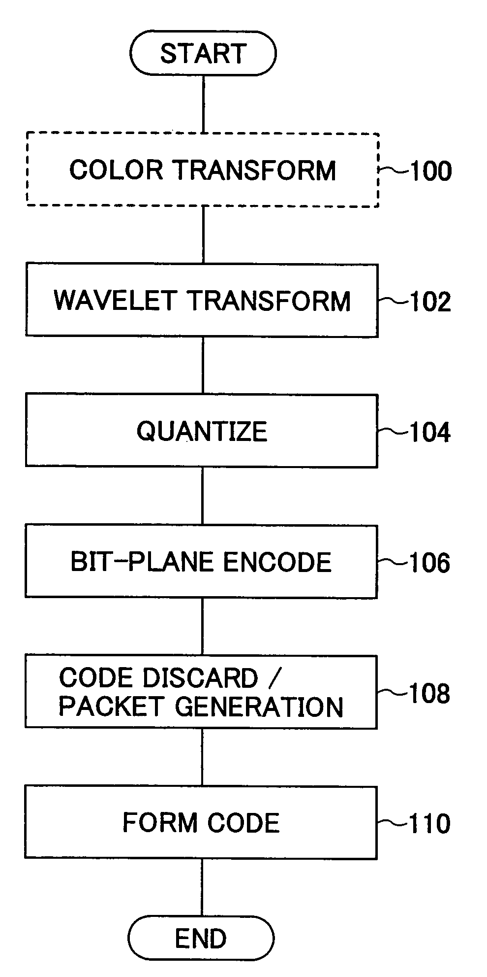
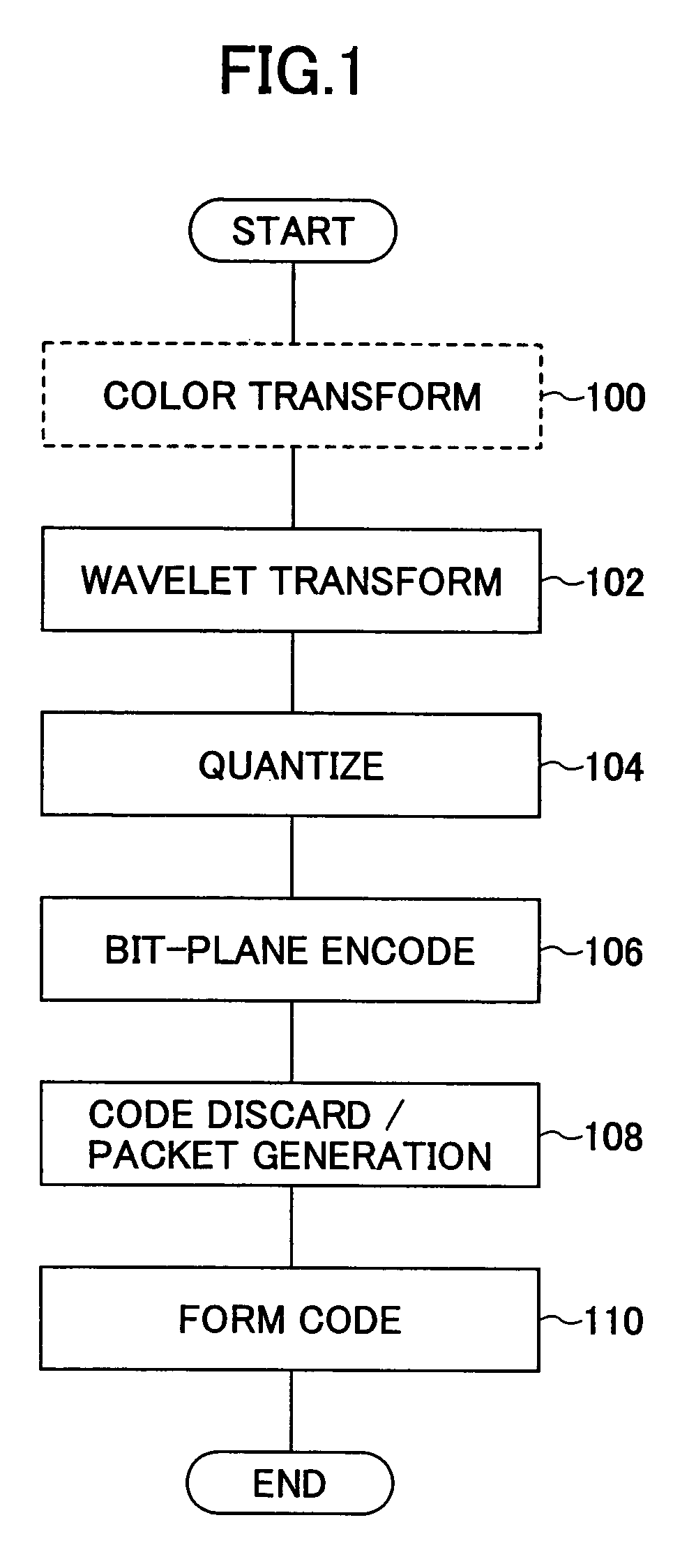
[0012]An image compression method and apparatus capable of reducing tile boundary distortion is described. In one embodiment, the image compressing apparatus divides an image into plural tiles, decomposing each of the tiles into plural sub bands by frequency conversion, and applies bit plane encoding to each of the sub bands for each encoding unit. The image compresses apparatus comprises a code discarding unit to selectively discard a code obtained by the bit plane encoding for each encoding unit, where the code discarding unit includes a discard amount setting unit that makes generally even the amount of code discarding in those encoding units that are in mutually adjacent relationship across a tile boundary.

Problems solved by technology

In JPEG 2000, on the other hand, there exits a problem in that discontinuity of images becomes observable in the decompressed image at the tile boundary in the case the compression ratio is increased (tile boundary distortion).
It should be noted that such tile boundary distortion is caused primarily as a result of an increase in the quantization error of the wavelet coefficients at the tile edge, while such an increase of the quantization error is caused as a result of the procedure of interpolating the picture element values or coefficient values by using a process called mirroring at the time of performing the wavelet transformation of each tile.
Another reason the tile boundary distortion is caused is the influence of the code discard processing.
However, even in the case where the process disclosed in the U.S. Pat. No. 5,710,835 or Japanese Laid Open Patent Application 2002-374532 is employed, there still arises cases in which the tile boundary distortion cannot be suppressed sufficiently due to the effect of the foregoing code discarding process.

Method used


Image

  • Image compression method capable of reducing tile boundary distortion
  • Image compression method capable of reducing tile boundary distortion
  • Image compression method capable of reducing tile boundary distortion

Examples


Embodiment Construction

[0041]Accordingly, one or more embodiments of the present invention include a novel and useful image compression method and apparatus wherein the foregoing problems are eliminated.

[0042]Another and more specific embodiments of the present invention include an image compression method and apparatus capable of suppressing the tile boundary distortion caused by the code discard processing effectively.

[0043]An embodiment of the present invention includes an image compression apparatus that compresses images by an image-encoding algorithm, where the image-encoding algorithm divides an image into plural tiles, decomposes each tile into plural sub bands by frequency conversion, and conducts bit-plane encoding for each of the sub-bands. The sub-band forms an encoding unit. The image compression apparatus comprises a code discarding unit for discarding a code obtained by the bit plane encoding selectively in each encoding unit. The code discarding unit includes trimming units for trimming a ...


PUM


Abstract

An image compressing apparatus divides an image into plural tiles, decomposes each tile into plural sub band by frequency conversion, and conducts bit plane encoding of each sub band for each encoding unit, wherein the image compressing apparatus includes a code discarding unit selectively discarding a code obtained by the bit plane encoding for each encoding unit, and wherein the code discarding unit includes a discard amount setting unit that makes generally even the amount of code discarding in the encoding units that are in mutually adjacent relationship across a tile boundary.

Description

[0001]The present application claims priority to the corresponding Japanese Application No. 2003-097151, filed on Mar. 31, 2003, the entire contents of which are hereby incorporated by reference.BACKGROUND OF THE INVENTION[0002]The present invention generally relates to compression of images and more particularly to a code discarding processing used in an image compression process conducted by an image encoding algorithm that divides an image into tiles and decomposes each tile into sub bands by frequency conversion and further conducts bit-plane encoding of the coefficients for the sub-bands in each encoding unit.[0003]As an example of this type of image encoding process, a JPEG 2000 encoding algorithm is known. It should be noted that the JPEG-2000 algorithm has become an international standard in 2001 (basic specification: ISO / IEC FCD 15,444-1). For more information about JPEG 2000, reference should be made to Yasuyuki Nomizu, “JPEG 2000, Next Generation Image Encoding Method,” F...

Claims


Application Information

Patent Timeline
Patent Type & Authority Patents(United States)
IPC IPC(8): G06K9/36G06K9/46H04B1/66H04N11/02H04N11/04H04N7/12H03M7/30H04N1/41H04N19/19H04N19/34H04N19/60H04N19/635
CPCH04N19/645H04N19/63H04N19/647H04N19/13
Inventor SAKUYAMA, HIROYUKIINOUE, TAKAOAOKI, SHINIKEBE, KEIICHIKODAMA, TAKUKOYAMA, TAKESHIYAMASHIRO, IKUKOMAKI, TAKASHITAKAHASHI, AKIRAYANO, TAKANORI
Owner RICOH KK
Learn More