Demodulation timing generation circuit and demodulation apparatus

a timing generation circuit and demodulation technology, applied in the direction of amplitude demodulation, synchronisation signal speed/phase control, orthogonal multiplex, etc., can solve the problems of deterioration of receiving performance, difficult detection of accurate timing, small peak of correlation, etc., to achieve high compliancy and stability

Inactive Publication Date: 2008-02-26
SONY CORP
View PDF24 Cites 27 Cited by
  • Summary
  • Abstract
  • Description
  • Claims
  • Application Information

AI Technical Summary

Benefits of technology

[0024]A first object of the present invention is to provide a demodulation timing generation circuit capable of generating correctly and with high precision a timing for demodulating a reception signal even under various kinds of reception conditions and a demodulation apparatus using the same.
[0025]A second object of the present invention is to provide a demodulation timing generation circuit high in compliancy and stability capable of stably and continuously maintaining frame synchronization once established and preventing the transmitting / receiving of data from interruption under conditions in which the condition of a channel is unstable, and a demodulation apparatus using the same.
[0080]Synchronization high in compliancy and stability can thus be obtained.

Problems solved by technology

This is because offset of the FFT timing leads to inter-symbol interference (ISI) or symbol rotation and therefore leads to the deterioration of the receiving performance.
On the other hand, the cross-correlation does not detect the correlation of noise and unrelated data, however, when there is a large offset in a reception frequency and a reception wave is changed due to reflection and fading, a peak of the correlation tends to become small.
In this manner, since the auto-correlation and cross-correlation are affected by the reflection at a channel, S / N, etc., in the above explained method of using the threshold value for generating the FFT timing, there is encountered a disadvantage that a low threshold value that can be used commonly under various transmission conditions must be set and detecting an accurate timing is difficult.
(1) In wireless communications, synchronization of every frame cannot always be detected due to the effects of channel conditions such as the occurrence of the above explained fading.
(2) In the above-mentioned system of 5 GHz, to make the system inexpensive, not a high precision crystal oscillator TCXO with temperature compensation, but crystal is used. On account of this, a reference frequency offset between a base station and a mobile station becomes a maximum 40 ppm. This means that the frequency shifts by four clocks in 100,000 clocks. Depending on the frame period, if this offset is not corrected well, the frame synchronization will easily be lost.
(3) If the frame synchronization is lost, more than the usual number of frames will be needed to obtain another synchronization. During that time, a large amount of data transfer will be interrupted.
In a best effort system, transferring the data again will do, however, this becomes a fatal problem if there is a desire to guarantee a certain degree of QoS (Quality of Service).

Method used


Image

  • Demodulation timing generation circuit and demodulation apparatus
  • Demodulation timing generation circuit and demodulation apparatus
  • Demodulation timing generation circuit and demodulation apparatus

Examples


first embodiment

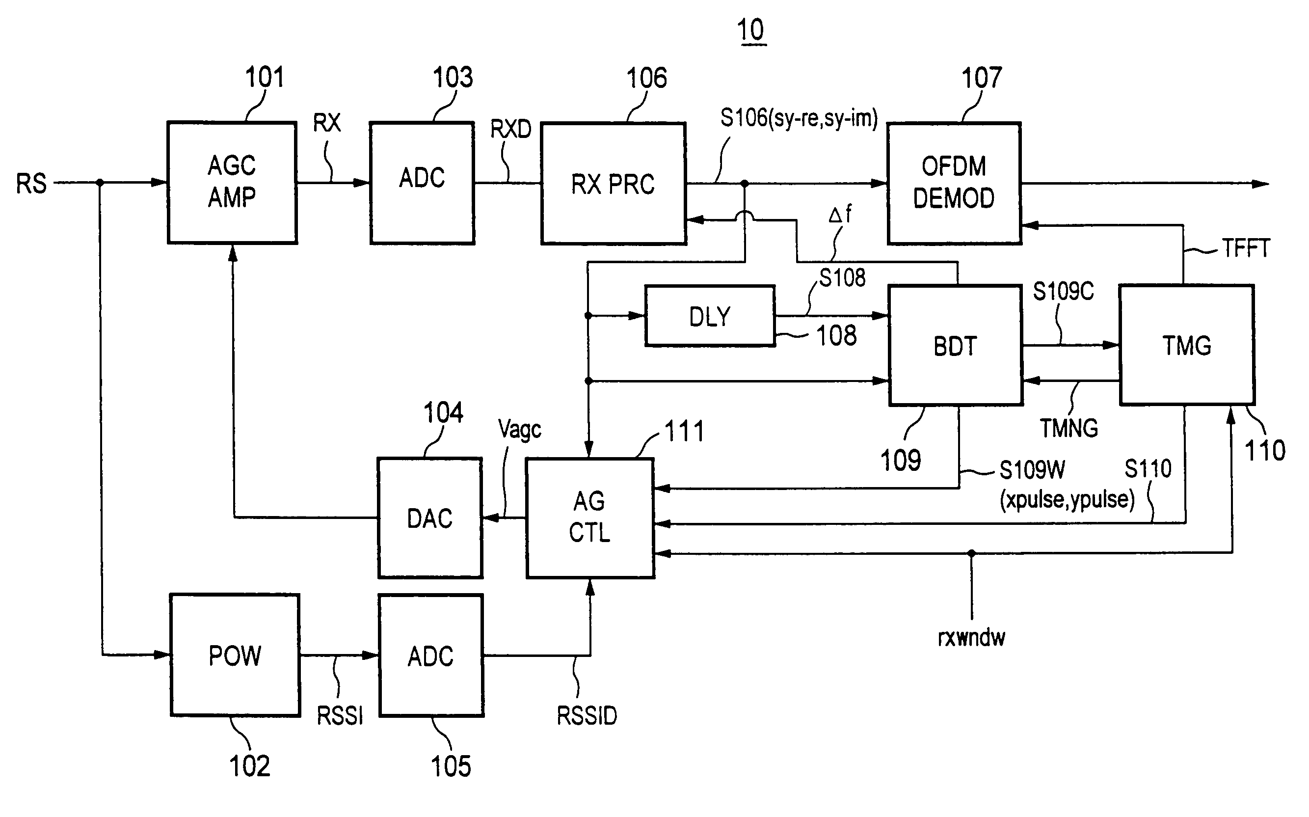
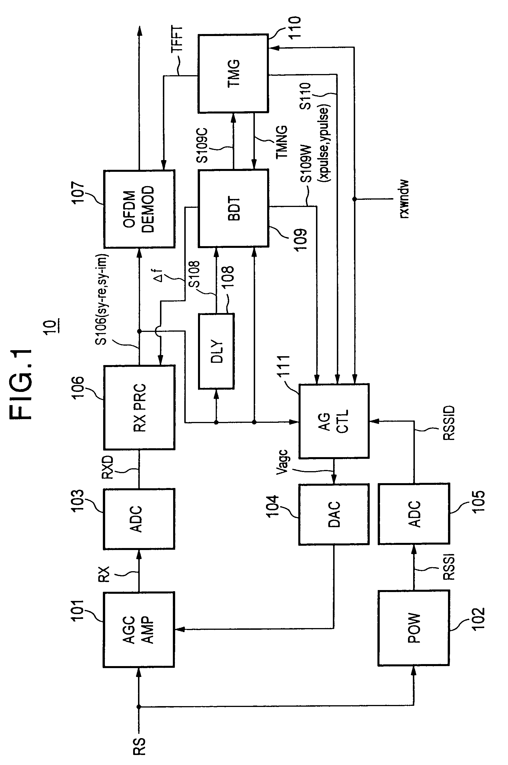
[0117]FIG. 1 is a block diagram of the configuration of a first embodiment of a burst synchronization demodulation apparatus to which an FFT timing generation circuit according to the present invention is applied.

[0118]The burst synchronization demodulation apparatus 10, as shown in FIG. 1, comprises as its main components an automatic gain control amplifier (AGCAMP) 101, a reception signal power monitor (POW) 102, an analog-to-digital (A / D) converter (ADC) 103, a digital-to-analog (D / A) converter (DAC) 104, an A / D converter (ADC) 105, a reception signal processing unit (RXPRC) 106, an OFDM demodulator (DEMOD) 107, a delay unit (DLY) 108, a burst detector (BDT) 109, a timing controller (TMG) 110, and an amplification gain controller (AGCTL) 111.

[0119]Below, an outline of the optimization of an automatic gain control system, a transmission (reception) signal, and an FFT timing of a burst synchronization communication system adopted in the present embodiment and the specific configura...

second embodiment

[0388]FIG. 26 is a block diagram of the configuration of a second embodiment of a burst synchronization demodulation apparatus to which the FFT timing generation circuit according to the present invention is applied. Further, FIG. 27 is a circuit diagram of an example of the concrete configuration of a burst detector and a timing controller of FIG. 26 according to the second embodiment.

[0389]The present second embodiment is different from the above explained first embodiment in the point that a frame synchronization function is added to the burst detector and the timing controller.

[0390]Specifically, in the present second embodiment, by calculating cross-correlation of frame synchronization data (already known) and input data, detecting a peak only for values in a detection window and exceeding a detection threshold value, and setting a detection window based on a frame period counted by a reference clock of a receiving side (mobile station side) after synchronization is established...


PUM


Abstract

A demodulation timing generation circuit capable of generating correctly and with high precision a timing for demodulating a reception signal even under various kinds of reception conditions and a demodulation apparatus using the same, wherein AGC control and frequency offset correction are performed by the burst detector 109 and the amplification gain controller 111 using a synchronization training signal (burst signal) added to the head of the reception signal (packet), a detection window period is provided for cross-correlation detection to detect the peak of the cross-correlation in the detection window DW by the timing controller 110, and in the end (rear edge) of the window, data corresponding to the peak position is loaded in the counter 11003 for counting the OFDM symbol interval. Due to this, it is possible to set an optimal FFT timing irrespective of the condition of a channel.

Description

TECHNICAL FIELD[0001]The present invention relates to a demodulation timing generation circuit and a demodulation apparatus applied to a receiver etc. of a wireless communication system, more particularly relates to a demodulation timing generation circuit and a demodulation apparatus applied to a wireless communication system etc. for receiving, for example, a radio signal which is modulated by an orthogonal frequency division multiplexing (OFDM) modulation method and includes a burst signal including a preamble signal at the header of this modulated packet signal.BACKGROUND ART[0002]The OFDM modulation method is a modulation method applies an inverse Fourier transform to 2n primary modulated (QPSK, 16ASAM, etc.) transmitted signal symbols to form 2n number of subcarriers orthogonal to each other on the frequency axis.[0003]In a wireless communication system adopting such a OFDM modulation system, a transmitting side subjects transmission data to serial-parallel conversion and perf...

Claims


Application Information

Patent Timeline
Patent Type & Authority Patents(United States)
IPC IPC(8): H03D1/00H04L27/06H04B7/26H04J11/00H04L7/10H04L27/26
CPCH04L27/2656H04L27/2662H04L27/2675
Inventor WAKAMATSU, MASATAKA
Owner SONY CORP
Why Eureka
Try Eureka