Disk mirror architecture for database appliance with locally balanced regeneration

a database appliance and locally balanced technology, applied in error detection/correction, redundant hardware error correction, instruments, etc., can solve problems such as inaccessibility of the whole system, and achieve the effect of increasing the general speed of the system

Inactive Publication Date: 2008-02-26
INT BUSINESS MASCH CORP
View PDF31 Cites 13 Cited by
  • Summary
  • Abstract
  • Description
  • Claims
  • Application Information

AI Technical Summary

Benefits of technology

[0004]The RAID systems typically configure mirroring architecture without considering the arrangement of the data on the drive. Data is read from and written to the disk at a constant bit rate. However, the tracks of a disk are not all the same size. Inner tracks can be a few inches smaller than outer tracks. If one rotation of the disk takes N seconds, more data is read from or written to the longer track per second than from or to the shorter track. Thus, the data transfer time differs dependent on the physical location of the data on the disk. Thus placing the mirror segments on the shorter tracks, according to one embodiment of the present invention, may increase the general speed of the system.

Problems solved by technology

In case of a RAID controller failure, the whole system may be inaccessible while the controller is being replaced.

Method used


Image

  • Disk mirror architecture for database appliance with locally balanced regeneration
  • Disk mirror architecture for database appliance with locally balanced regeneration
  • Disk mirror architecture for database appliance with locally balanced regeneration

Examples


Embodiment Construction

[0027]A description of preferred embodiments of the invention follows.

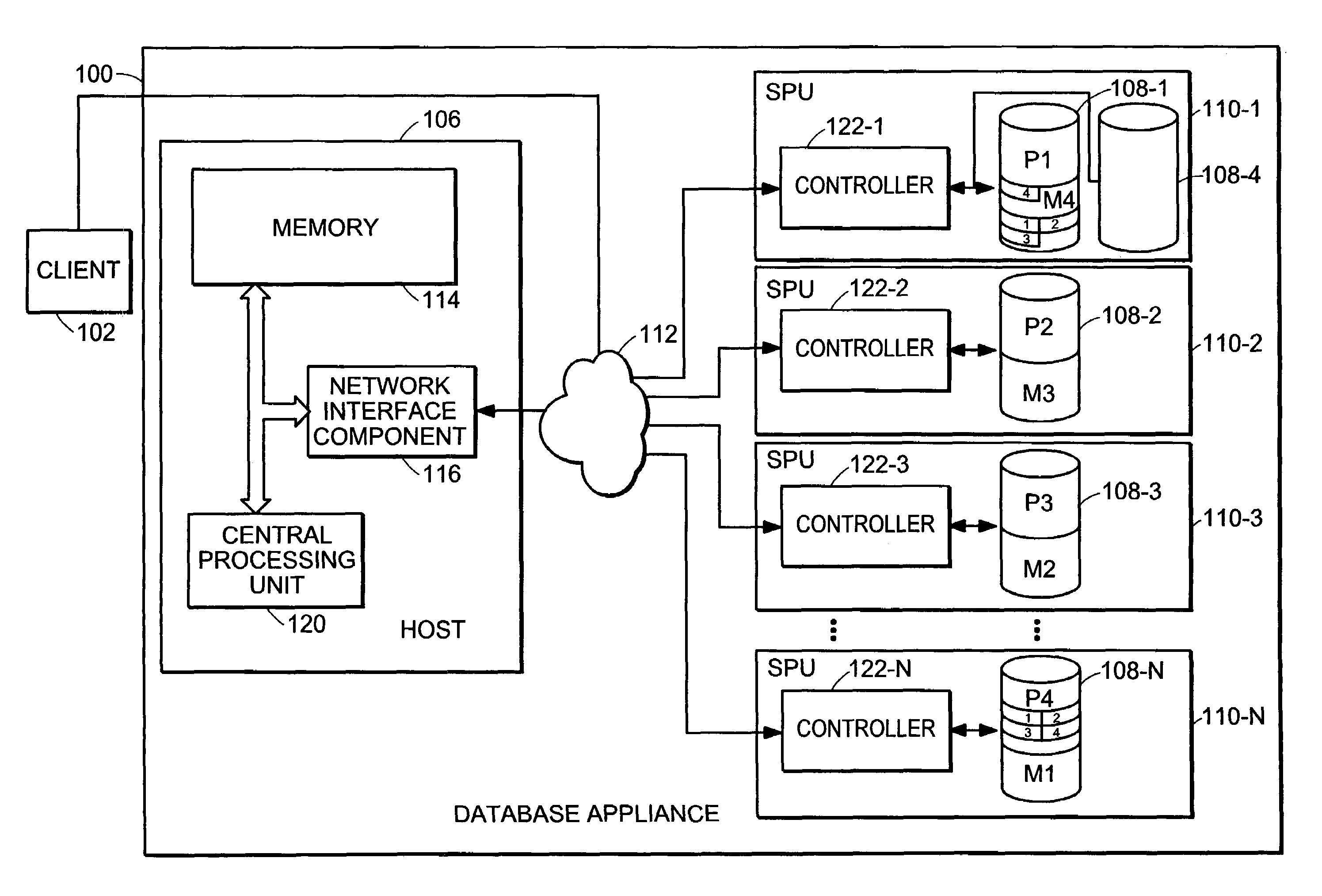
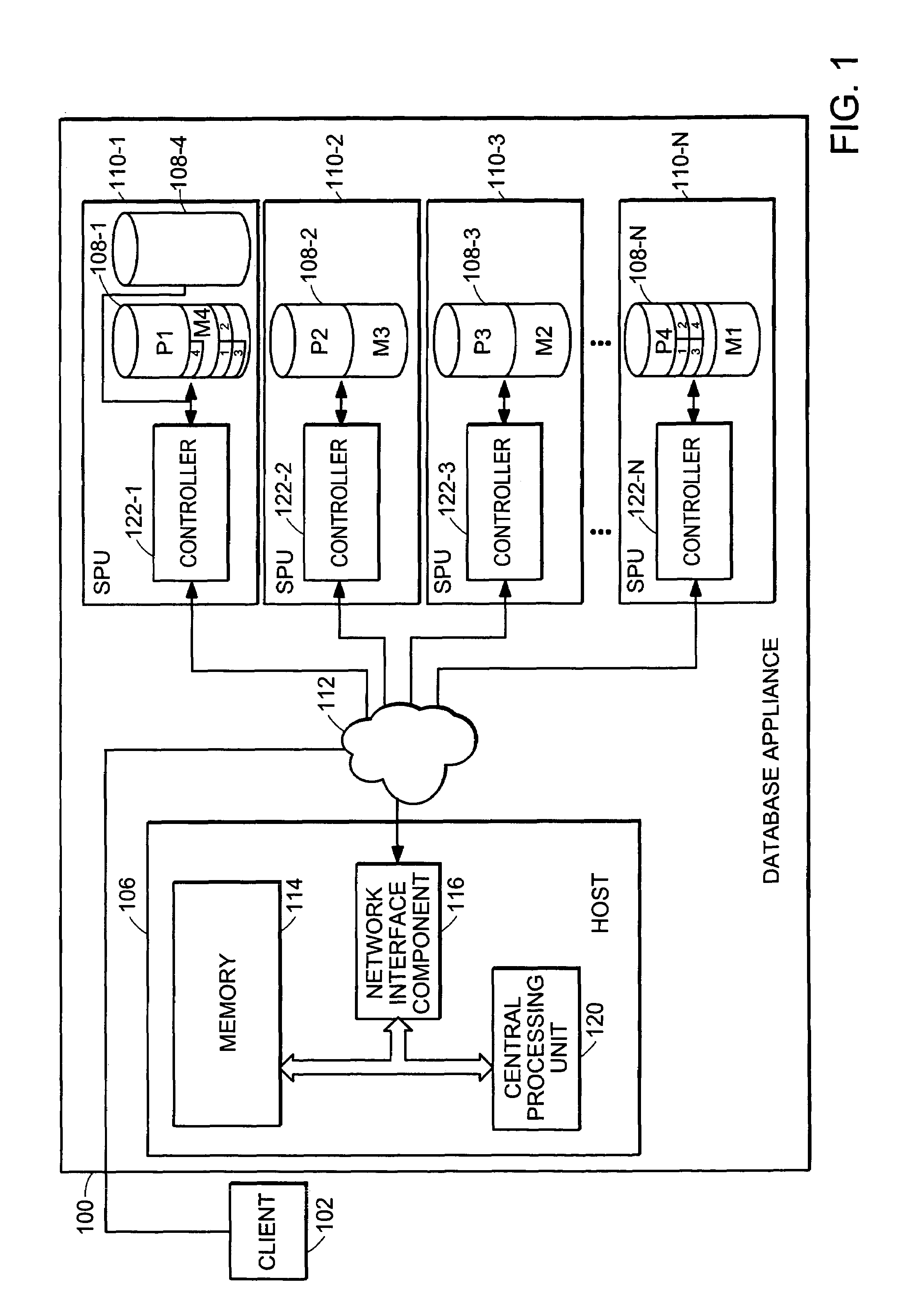
[0028]FIG. 1 is a block diagram of a database appliance 100 according to the principles of the present invention. The database appliance 100 includes a host 106 for processing database requests received from a client 102 and a plurality of disk drives 108-1, . . . , 108-n storing the database. Each of the plurality of disk drives 108-1, . . . 108-n is coupled to a respective Controller 120-1, . . . 120-n. Each Snippet Processing Unit (SPU) 110-1, . . . 110-n forms a processing assembly that includes a respective controller 122-1, . . . 122-n and at least one disk drive. In the embodiment shown, controllers 122-2, 122-3 and 122-n are each coupled to one disk drive and controller 122-1 is coupled to two disk drives. Each SPU is coupled to a host 106 through a data communication network. 112. The SPU performs the primitive functions of a query to the database, controlling all aspects of reading from and writing to a ...


PUM


Abstract

A disk is segmented into a first data segment and a secondary data segment. The secondary data segment stores a logical mirror of the first data segment of another disk. Upon detecting a failure, the logical mirror of data stored in the first data segment of the failed disk is accessible from the secondary data segment of a non-failed disk. The first data segment can be rebuilt quickly on another disk from the logical mirror stored in the secondary data segment. During regenerating, accesses to the first data segment on the disk containing the logical mirror are handled by its own logical mirror, which is not involved in the regenerating process.

Description

RELATED APPLICATION(S)[0001]This application is a continuation-in-part of U.S. application Ser. No. 10 / 667,127, filed on Sep. 18, 2003 now U.S. Pat. No. 7,089,448, which claims the benefit of U.S. Provisional Application No. 60 / 411,743, filed on Sep. 18, 2002. The entire teachings of the above-applications are incorporated herein.BACKGROUND OF THE INVENTION[0002]A Redundant Array of Inexpensive Disks (RAID) provides highly available data by distributing data amongst a plurality of disks using a method defined by one of a plurality of RAID levels. In a system implementing RAID level 1, each disk in the system has an associated mirror disk, all data written to the primary disk being replicated on the mirror disk.SUMMARY OF THE INVENTION[0003]RAID systems typically have a single hardware controller controlling which data goes to which disks. The topology of the disk mirroring is pre-set and, in case of a fault, a replacement disk needs to be connected in order to provide the same level...

Claims


Application Information

Patent Timeline
Patent Type & Authority Patents(United States)
IPC IPC(8): G06F11/00G06F11/20
CPCG06F11/2058G06F11/2069G06F11/2071G06F11/2082
Inventor ZANE, BARRY M.HINSHAW, FOSTER D.MACDONALD, PHILIP J.METZGER, JOHN K.
Owner INT BUSINESS MASCH CORP
Why Eureka
Try Eureka