Building construction system

a construction system and building technology, applied in the direction of building repairs, liquid handling, and closure using stoppers, can solve the problems of limiting the '043 process to maintaining the vertical orientation of the assembled form system, and the '043 process is therefore extremely slow in producing a building wall, and achieves accurate pattern guide

Active Publication Date: 2008-03-04
INTEPLAST GROUP
View PDF53 Cites 30 Cited by
  • Summary
  • Abstract
  • Description
  • Claims
  • Application Information

AI Technical Summary

Benefits of technology

[0030]The structural forming assembly of the invention comprises wall molding means for forming laterally spaced, opposed molding surfaces that define a wall mold cavity for forming a wall structure. The wall molding means includes panel holding means for vertically disposing laterally spaced wall forming panels to provide the molding surfaces along opposed sides of the wall mold cavity. The cavity has an upwardly directed top opening into which hardenable material is to be poured and hardened to produce the wall structure within the wall mold cavity. Reinforcement rod suspending means is for freely positioning and retaining horizontally and freely disposed reinforcement rod means at a preselected horizontal location spaced inwardly from each opposed molding surface within the mold cavity. Means for attaching the rod suspending means to the opposed wall forming panels is for locating the horizontally disposed rod means at spaced preselected vertical locations between the spaced molding surfaces. The rod suspending means is effective to retain reinforcement rod means in place at the preselected horizontal and vertical locations while the hardenable material is being poured into and allowed to harden within the mold cavity.
[0033]A particular device of the invention comprises reinforcement rod suspending means for freely positioning and horizontally disposing reinforcement rod means within a wall mold cavity at a preselected horizontal location between each opposed molding surface and at a plurality of preselected vertical locations spaced upwardly along opposed wall forming panels. The device includes fastening means for attaching the reinforcement rod suspending means to each of the opposed wall molding panels to retain the reinforcement rod means in place between wall forming panels at the preselected horizontal and vertical locations while hardenable material is being poured into and allowed to harden within the mold cavity.

Problems solved by technology

Until the current invention such poured-in-place concrete methods have been limited to methods that are quite costly of time, labor, and materials.
Such bracing is limited to maintaining the vertical orientation of the assembled form system.
The '043 process is thus extremely slow in producing a building wall.
Each of the foregoing prior art systems are generally time-consuming with respect to preparation of the forming assemblies either at or remote from the building site; expensive moving and transporting equipment is needed to handle the forming equipment and / or completed modular constructions being moved to the building site; and skilled craftsmen are required to use sophisticated molding equipment to prepare for and effect the placement of hardenable material into the particular mold cavity.

Method used


Image

  • Building construction system
  • Building construction system
  • Building construction system

Examples


Embodiment Construction

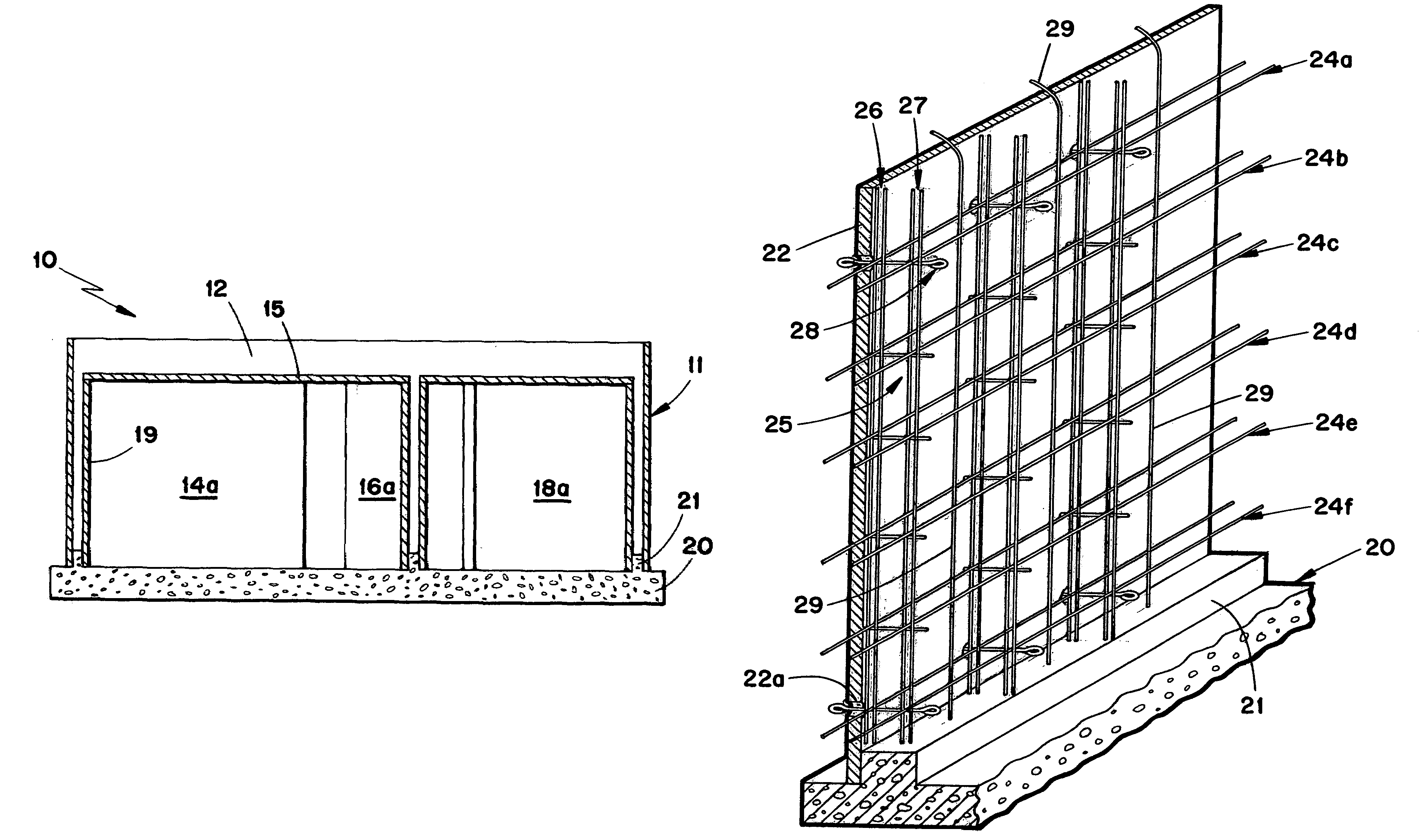
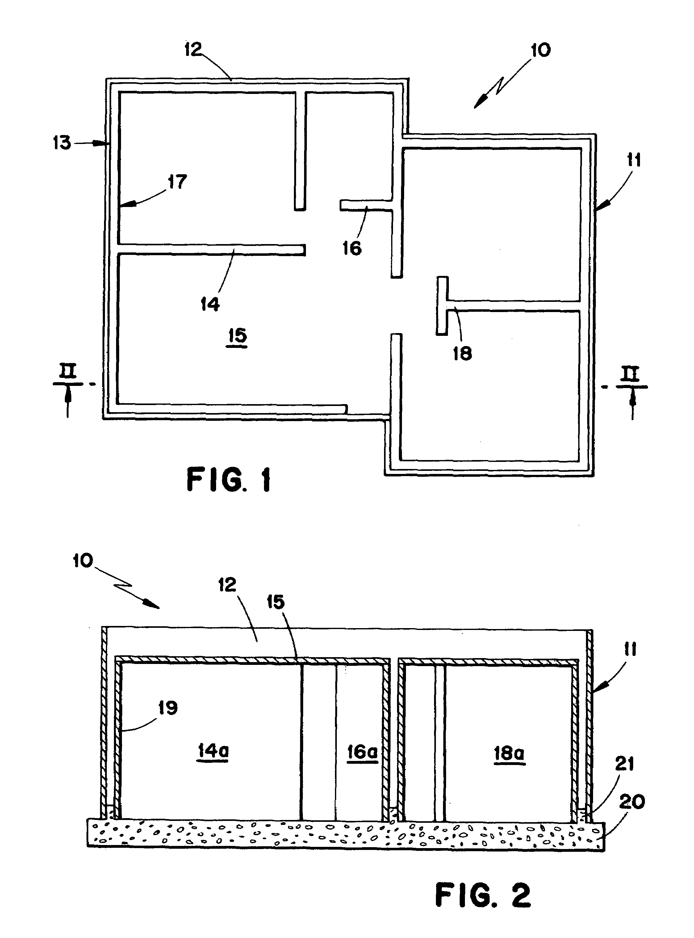
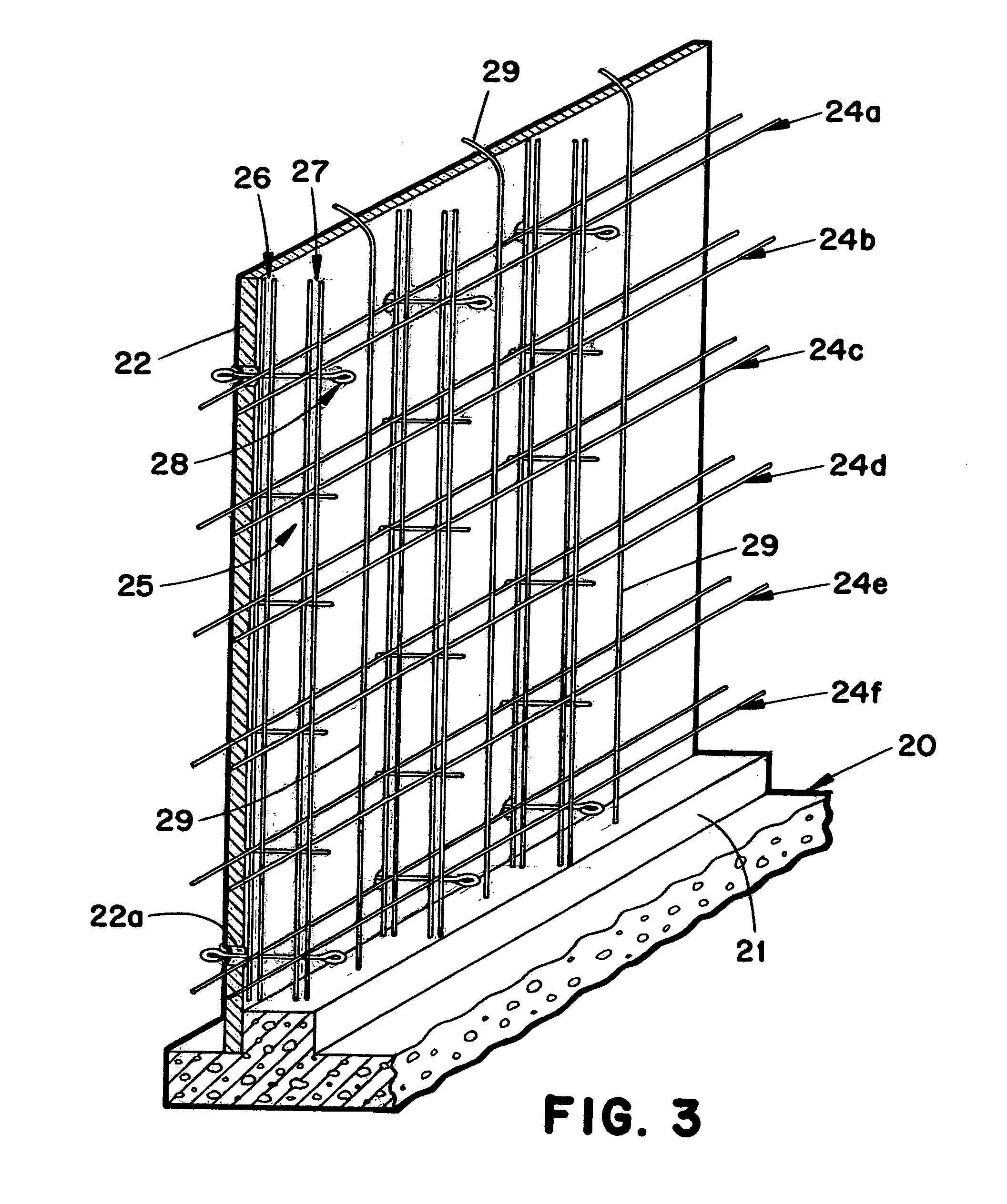
[0055]The structural forming assembly, generally designated 10, of FIGS. 1 and 2 includes an upper building structure 11 disposed on a concrete slab 20 having upstanding wall portions 21 that define the internal and external wall segments in accord with the preselected building floor plan as shown. Slab 20 with wall portions 21 is made using well known concrete mold fabrication techniques at the building site. Yet in recent years the prior art has developed sophisticated off-site methods of fabricating building modules that are transported to and erected on the building site to avoid formerly cumbersome poured-in-place techniques that are labor intensive thus cost ineffective until now.

[0056]Molding assembly 10 with its unique layout of upstanding slab wall portions 21, however, provides a means to quickly form laterally spaced, opposed molding surfaces that define an upper building mold cavity having an exterior wall profile 13 and an interior wall profile 17 of a wall and ceiling ...


PUM


Abstract

A structural forming assembly comprises wall molding panels for forming laterally spaced, opposed molding surfaces that define a wall mold cavity for forming a wall structure. The wall panels are vertically disposed and laterally spaced to provide the molding surfaces along opposed sides of the wall mold cavity. Reinforcement rod suspending grid elements attached to the opposed wall forming panels are for freely positioning and retaining horizontally and freely disposed reinforcement rods at a preselected horizontal location spaced inwardly from each opposed molding surface within the mold cavity, and at spaced preselected vertical locations between the molding surfaces. The rod suspending elements are effective to retain reinforcement rods in place at the preselected horizontal and vertical locations while the hardenable material is being poured into an upwardly directed top mold opening and allowed to harden within the wall mold cavity. The invention includes a fixed construction that comprises a monolithic building structure including a floor slab having a top surface, and an upper building portion having a ceiling slab and a wall structure, which extends along the floor top surface in a room layout of a building in accord with a preselected floor plan.

Description

FIELD OF THE INVENTION[0001]This invention relates to a method and apparatus for forming reinforced poured-in-place buildings for home and office. More particularly, the invention relates to a method and apparatus for producing a monolithic building on site using a unique poured-in-place fabrication technique using hardenable material such as concrete to form the desired novel constructions of the invention.BACKGROUND OF THE INVENTION[0002]The two major categories of concrete fabrication are poured-in-place concrete and pre-cast concrete. Poured-in-place concrete has the advantage of permitting a great deal of flexibility as to the form or shape of the structure being made. Until the current invention such poured-in-place concrete methods have been limited to methods that are quite costly of time, labor, and materials.[0003]U.S. Pat. No. 3,089,217 discloses the common poured-in-place practice of erecting a form system having parallel spaced panels interconnected by a tie system whic...

Claims


Application Information

Patent Timeline
Patent Type & Authority Patents(United States)
IPC IPC(8): E04C2/34E04B2/28E04G11/10E04G11/38E04G17/075
CPCE04G11/10E04G11/38E04G17/075
Inventor MOLINA, ENRIQUE
Owner INTEPLAST GROUP
Why Eureka
Try Eureka