Multi-cycle downhole apparatus

a multi-cycle, downhole technology, applied in the direction of fluid removal, borehole/well accessories, sealing/packing, etc., can solve the problems of limited axial piston movement, and damage to the control pin

Inactive Publication Date: 2008-03-04
SMITH INT INC
View PDF7 Cites 80 Cited by
  • Summary
  • Abstract
  • Description
  • Claims
  • Application Information

AI Technical Summary

Problems solved by technology

For example, this may be necessary where the desired fluid flow rate to drive a drilling tool is insufficient to carry all the drilled material up the annulus to the surface.
Furthermore, the extent of axial piston movement is limited by the groove profile.
A problem associated with the aforementioned prior art means for controlling the piston is that there can be a tendency for the control pin to become damaged within the control groove as a r...

Method used


Image

  • Multi-cycle downhole apparatus
  • Multi-cycle downhole apparatus
  • Multi-cycle downhole apparatus

Examples


second embodiment

[0074]Although the improvements shown in FIGS. 13 to 16 have been described as modifications to the third tool shown in FIGS. 9 to 12, the described modifications may also be advantageously applied to the tools shown in FIGS. 1 to 8. Indeed, the present invention shown in FIG. 17 is a modification of the tool shown in FIGS. 5 to 8 of the accompanying drawings. Apart from the modifications described below, the improved circulating sub 402 of FIG. 17 is substantially identical to the circulating sub 102 of FIGS. 5 to 8 and, accordingly, lice reference numerals have been used to identify like components in the accompanying drawings.

[0075]As with the first embodiment 302, the second embodiment 402 comprises two sets of vent holes 468,469 for venting the piston spring chamber. The set of vent holes 469 provided in the body comprises a single vent hole. Each hole of the second set of vent holes 468 is occluded with a NPT plug. Also, the body of the sub 402 is provided with a set of apertu...

first embodiment

[0076]A further modification provided to the sub 402 is the provision of three sets of stabiliser blades 445 immediately downhole of the body aperture 440. Furthermore, the sleeve 426 may be provided in two components so as to ease manufacture. The two components of the sleeve 426 may be pinned or screw threadedly engaged with one another. The first embodiment shown in FIGS. 13 to 16 may also be provided with a multi-piece sleeve to assist with manufacture.

[0077]Furthermore, as already mentioned in relation to the tools of FIGS. 1 to 12, a dart may be run so as to block the piston bore and allow a sufficient build up of pressure to move a tool into the emergency closed configuration. The first embodiment of the present invention is shown in FIG. 16 located in the emergency closed configuration with a dart 390 blocking the piston bore 258. The dart 390 is shown in greater detail in FIG. 13 wherein it can be seen that the dart comprises a through bore 392 occluded at an uphole end the...


PUM


Abstract

A downhole apparatus which can be used as multi-cycle circulating subs utilized in downhole drilling operations, includes a piston (242) slidably mounted in a body between positions in which at least one aperture in the body is opened and closed. Movement of the piston (242) is controlled by a pin (86), secured to one of the body and a control member, and a control groove (52) formed in the other of the body and control member for receiving a portion of the pin. An arrangement of elements (232, 276) respectively connected to the control member and body is such as to normally resist axial movement of the control member from a first axial position to a second axial position. A spring (44) is located in a chamber for biasing the piston (242). The chamber is vented by an opening in the body.

Description

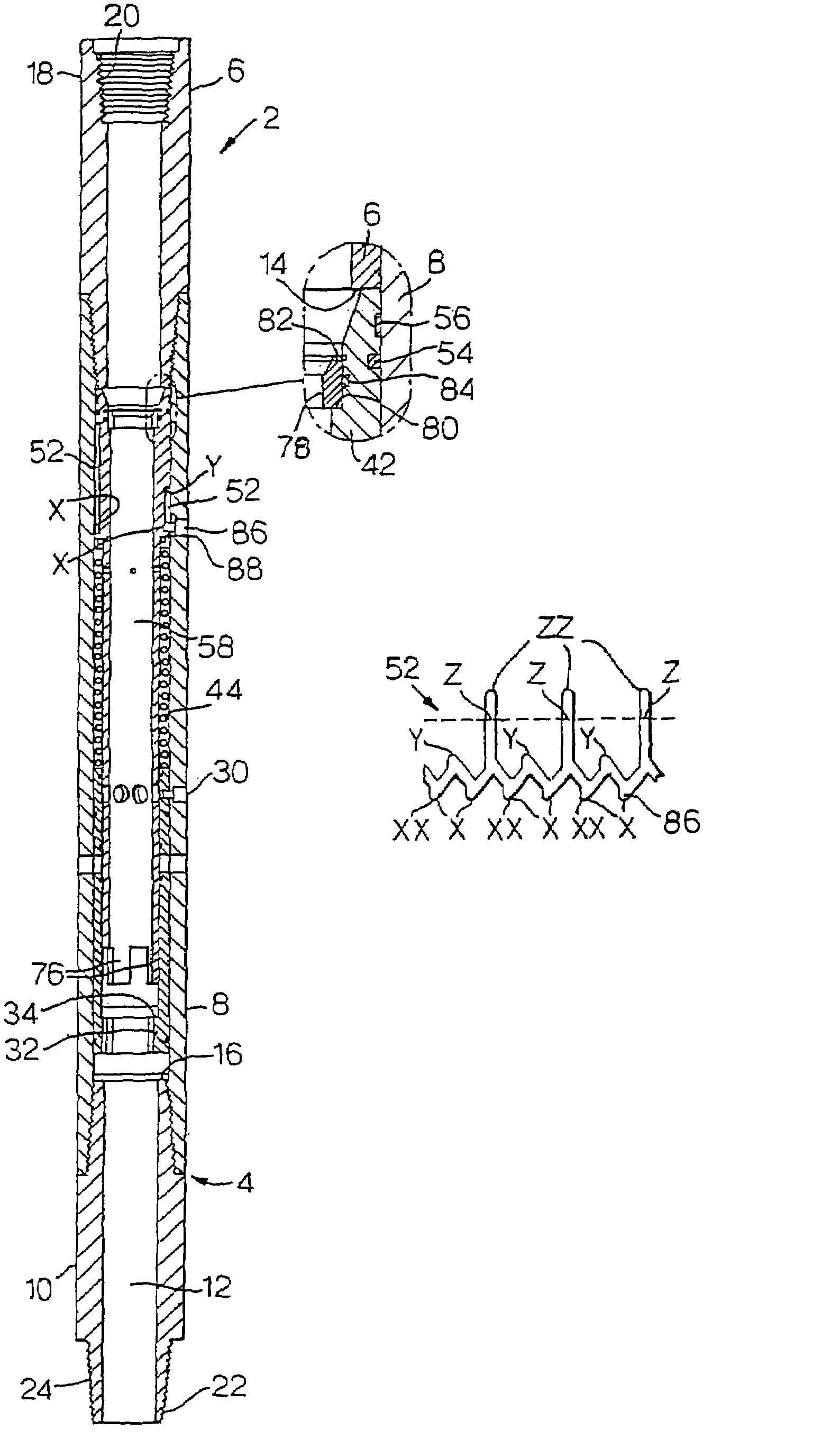
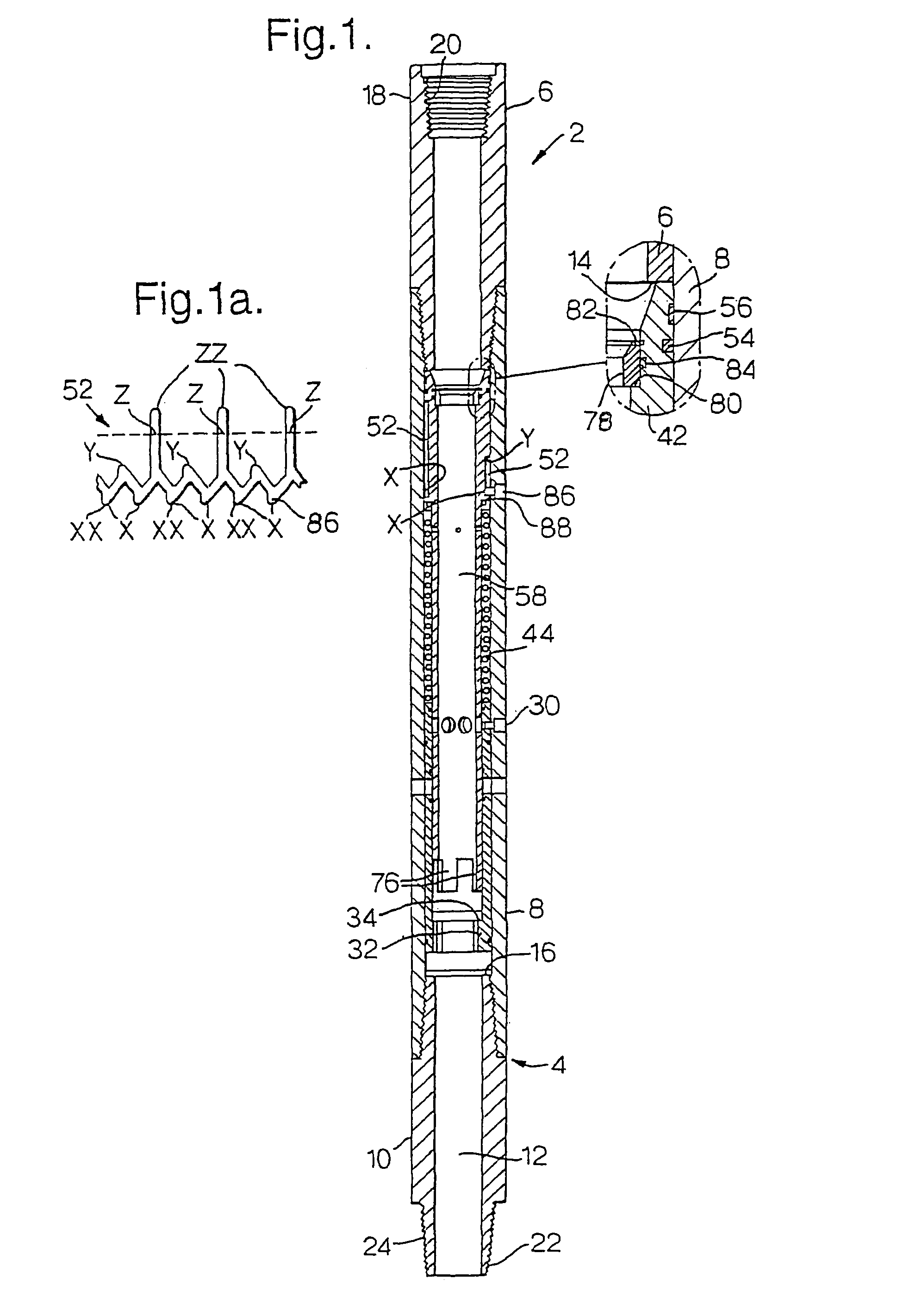
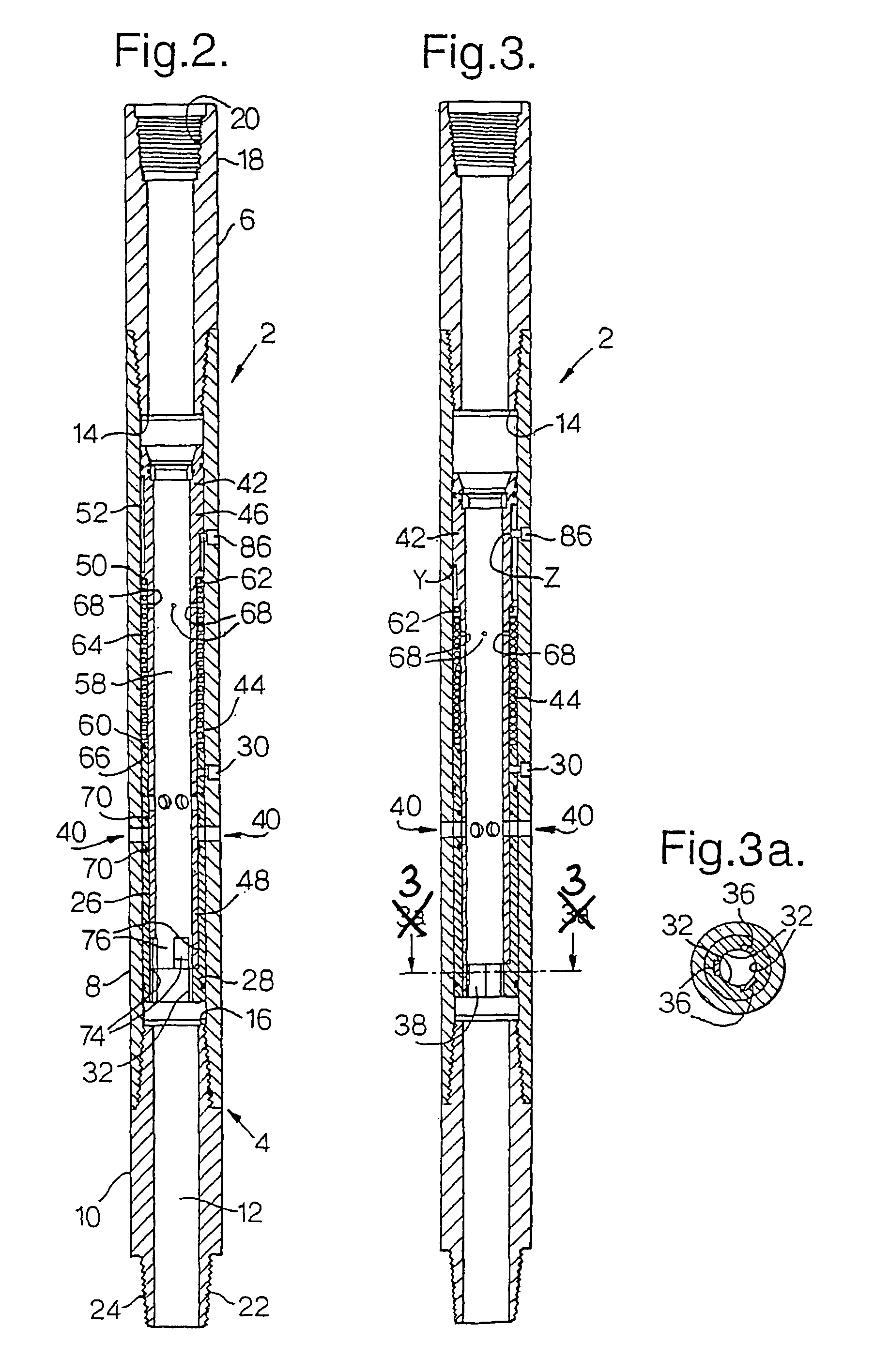
BACKGROUND OF THE INVENTION[0001]1. Field of the Invention[0002]The present invention relates to downhole apparatus and particularly, but not exclusively, to multi-cycle circulating subs used during downhole drilling operations.[0003]2. The Prior Art[0004]It is often necessary in downhole drilling operations to bypass or partially bypass the flow of wellbore fluid down the drill string into the wellbore annulus. For example, this may be necessary where the desired fluid flow rate to drive a drilling tool is insufficient to carry all the drilled material up the annulus to the surface. In these circumstances, a circulating sub may be used to allow the flow rate required to remove the drilled material to be pumped into the annulus whilst maintaining the lower flow rate required at the drilling tool.[0005]It is known to provide a circulating sub with an axially movable piston for opening and closing vent apertures. The vent apertures are provided in a body of the sub and allow wellbore ...

Claims


Application Information

Patent Timeline
IPC IPC(8): E21B34/12E21B21/10E21B23/00
CPCE21B21/103E21B23/006E21B23/004E21B34/10
Inventor MCGARIAN, BRUCETULLOCH, RORY MCCRAEGILLIES, IAN A.
Owner SMITH INT INC
Why Eureka
Try Eureka