Controllable antenna arrangement

a controllable and antenna technology, applied in the field of antenna arrangement, can solve problems such as patch antennas

Inactive Publication Date: 2008-03-04
NOKIA TECH OY
View PDF17 Cites 119 Cited by
  • Summary
  • Abstract
  • Description
  • Claims
  • Application Information

AI Technical Summary

Benefits of technology

[0009]The use of one or more strip or microstrip lines of different lengths is advantageous since the phase difference caused by the impedance of the strip or microstrip line leads to the desired effect of controllable impedance in the antenna arrangement. Control of the impedance which can result from using the invention is advantageous since the antenna element can be tuned accurately by suitable control of the switch.
[0011]The embodied antenna arrangements include a feed connection and a ground connection applied directly to the antenna element, with the switch being connected separately from either of these connections. This has the advantage that the switch causes loss only at the frequency band where the switching takes place. If the switch were to be associated with either the ground connector or the feed connector, all frequency bands of the antenna would suffer from the loss of the switch.

Problems solved by technology

However, the use of patch antennas presents a problem when the radiotelephone is required to operate in more than two multiple frequency bands, for example in the PCS and DCS bands as well as the GSM 900 band.

Method used


Image

  • Controllable antenna arrangement
  • Controllable antenna arrangement
  • Controllable antenna arrangement

Examples


Embodiment Construction

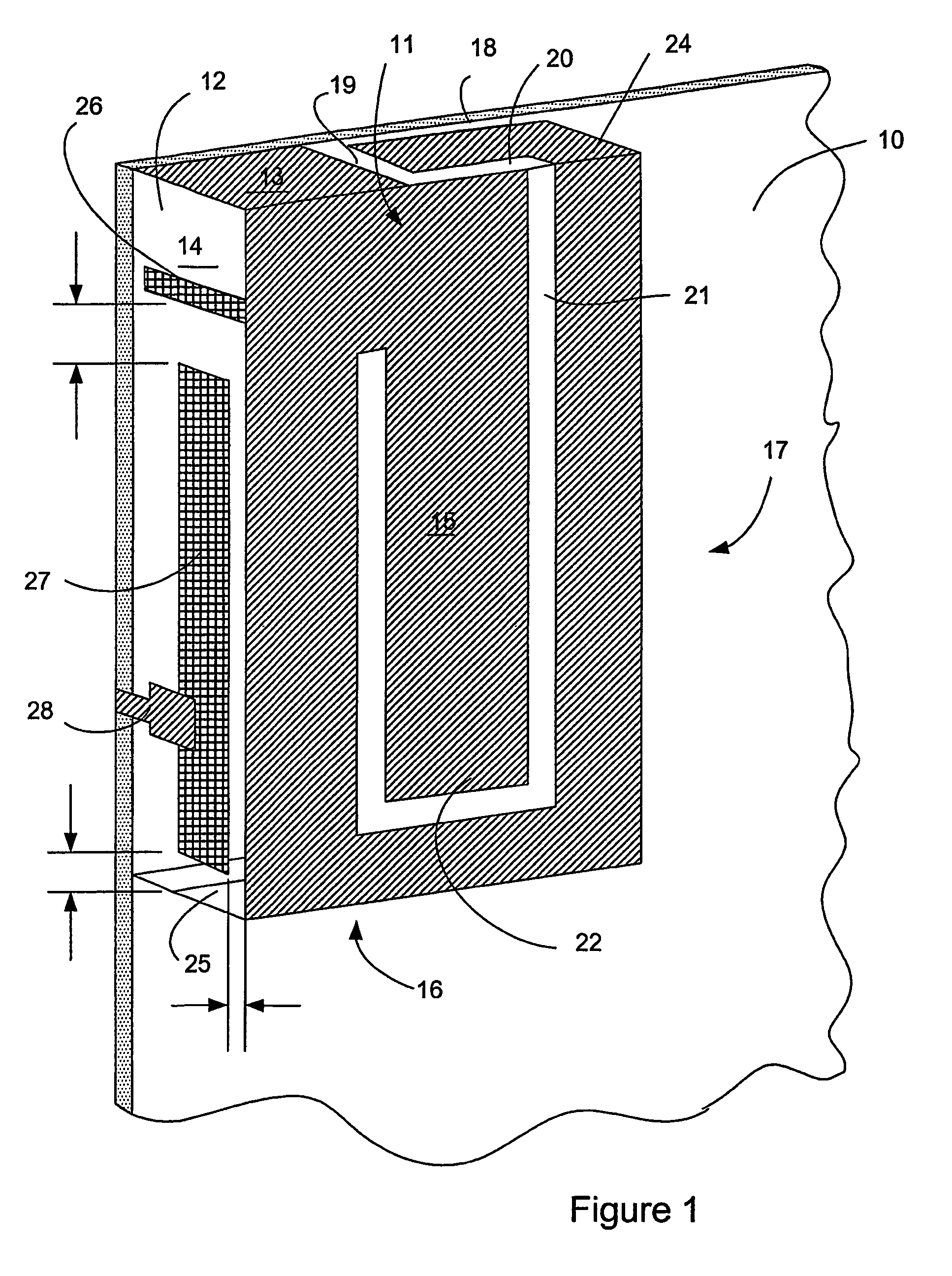
[0020]Referring firstly to FIG. 1, a printed wire board 10 is shown in perspective. Mounted on a front surface of the printed wire board 10 is an antenna. The antenna 11 comprises a substrate 12 comprised of a plastic, such as polycarbonate (PVC), having a three dimensional rectangular shape. A first face 13 of the substrate, which is upper-most shown in the drawing, has a length of 12 mm, adjoining printed wire board 10 on one side, and a height of 6 mm. A second face 14 of the substrate 12, which is leftmost shown in the drawing, has a length of 30 mm adjoining the printed wire board 10, and a height of 6 mm. One of the 6 mm high edges adjoins the first face 13. A third face 15, which adjoins the first and second faces 13, 14 and is opposite to the printed wire board 10, has a length 30 mm and a width 12 mm. A fourth face 16 is opposite to and has the same dimensions as the first face 13. A fifth face 17 is opposite to and has the same dimensions as the second face 14. The fifth f...


PUM


Abstract

An antenna (11) includes a patch antenna element (22) capacitively coupled to a load patch (27). A switch (33) connects the load patch (27) to one of one or more strip lines (35, 37, 40), each of which has a different length. Each strip lines causes the load patch (27) to have a different impedance, with one causing a short circuit, one causing an open circuit, and one causing an impedance in between these extremes. Different impedances of the load patch (27) cause different frequencies of operation of the antenna patch (22) by virtue of the capacitive coupling therebetween. The antenna (11) is thereby tuneable to three separate frequencies. Other frequency bands are unaffected by virtue of the location of the load patch (27) relative to the antenna patch (22). By allowing tuning by way of controlling the impedance of the load patch (27), the antenna arrangement can be made smaller than a corresponding passive antenna operable at the same frequencies. By using an N throw switch, N strip lines of different lengths can be connected, each giving rise to a different operating frequency.

Description

CROSS-REFERENCE TO RELATED APPLICATIONS[0001]This patent application claims priority under 35 U.S.C. §371 from international application No. PCT / EP2002 / 012985, filed Nov. 20, 2002.FIELD OF THE INVENTION[0002]This invention relates to an antenna arrangement, the frequency of which may be adjusted by control of a multiple throw switch connected to one or more strip or microstrip lines.BACKGROUND OF THE INVENTION[0003]It is relatively common for radiotelephone handsets to include internal patch antenna arrangements, since these are relatively inexpensive to manufacture and since they can have suitably narrow bandwidths at desired operating frequencies. However, the use of patch antennas presents a problem when the radiotelephone is required to operate in more than two multiple frequency bands, for example in the PCS and DCS bands as well as the GSM 900 band. The PCS band comprises the frequencies 1850 to 1990 MHz, and the DCS transmitter band comprises the frequencies 1710 to 1785 MHz,...

Claims


Application Information

Patent Timeline
Patent Type & Authority Patents(United States)
IPC IPC(8): H01Q1/38H01Q1/24H01Q5/00H01Q5/371H01Q5/378H01Q9/04H01Q19/00
CPCH01Q1/243H01Q9/0421H01Q9/0442H01Q5/378H01Q19/005H01Q5/371H01Q9/0457
Inventor SAGER, MADSTROELSEN, JENS
Owner NOKIA TECH OY
Why Eureka
Try Eureka