System and method for finger management in a rake receiver

a rake receiver and finger management technology, applied in the field of wireless receivers, can solve the problems of limiting the performance of modern mobile wireless communication systems, channel delays associated with multipath components are non-stationary, and unnecessarily deassigning of multipath components from rake receiver fingers

Active Publication Date: 2008-03-04
NAT SEMICON CORP
View PDF21 Cites 41 Cited by
  • Summary
  • Abstract
  • Description
  • Claims
  • Application Information

AI Technical Summary

Benefits of technology

[0016]According to a still further embodiment of the present invention, the controller is further capable of determining if the signal power of an assigned multipath signal assigned to a fourth finger of the RAKE receiver is less than a fade threshold value.
[0017]According to a yet further embodiment of the present invention, the controller, in response to a determination that the signal power of the assigned multipath signal is less than the fade threshold value, is further capable of determining a time duration during which the assigned multipath signals has been less than the fade threshold value.

Problems solved by technology

Signal fading due to variations in channel characteristics is a major factor limiting the performance of modern mobile wireless communication systems.
However, the channel delays associated with the multipath components are non-stationary.
However, the apparatus disclosed in the Vejlgaard et al. disclosure only takes finger power into account when making assignment decisions.
A very brief fast fading of a multipath component may cause the multipath component to be unnecessarily deassigned from a RAKE receiver finger.
Also, the prior art Vejlgaard et al. reference is wasteful of RAKE receiver fingers in that it assigns fingers by groups of three that do not move independently.
This increases the number of fingers required and also decreases the resolvability of the RAKE receiver fingers.

Method used


Image

  • System and method for finger management in a rake receiver
  • System and method for finger management in a rake receiver
  • System and method for finger management in a rake receiver

Examples


Embodiment Construction

[0027]FIGS. 1 through 6, discussed below, and the various embodiments used to describe the principles of the present invention in this patent document are by way of illustration only and should not be construed in any way to limit the scope of the invention. Those skilled in the art will understand that the principles of the present invention may be implemented in any suitably arranged mobile station RAKE receiver.

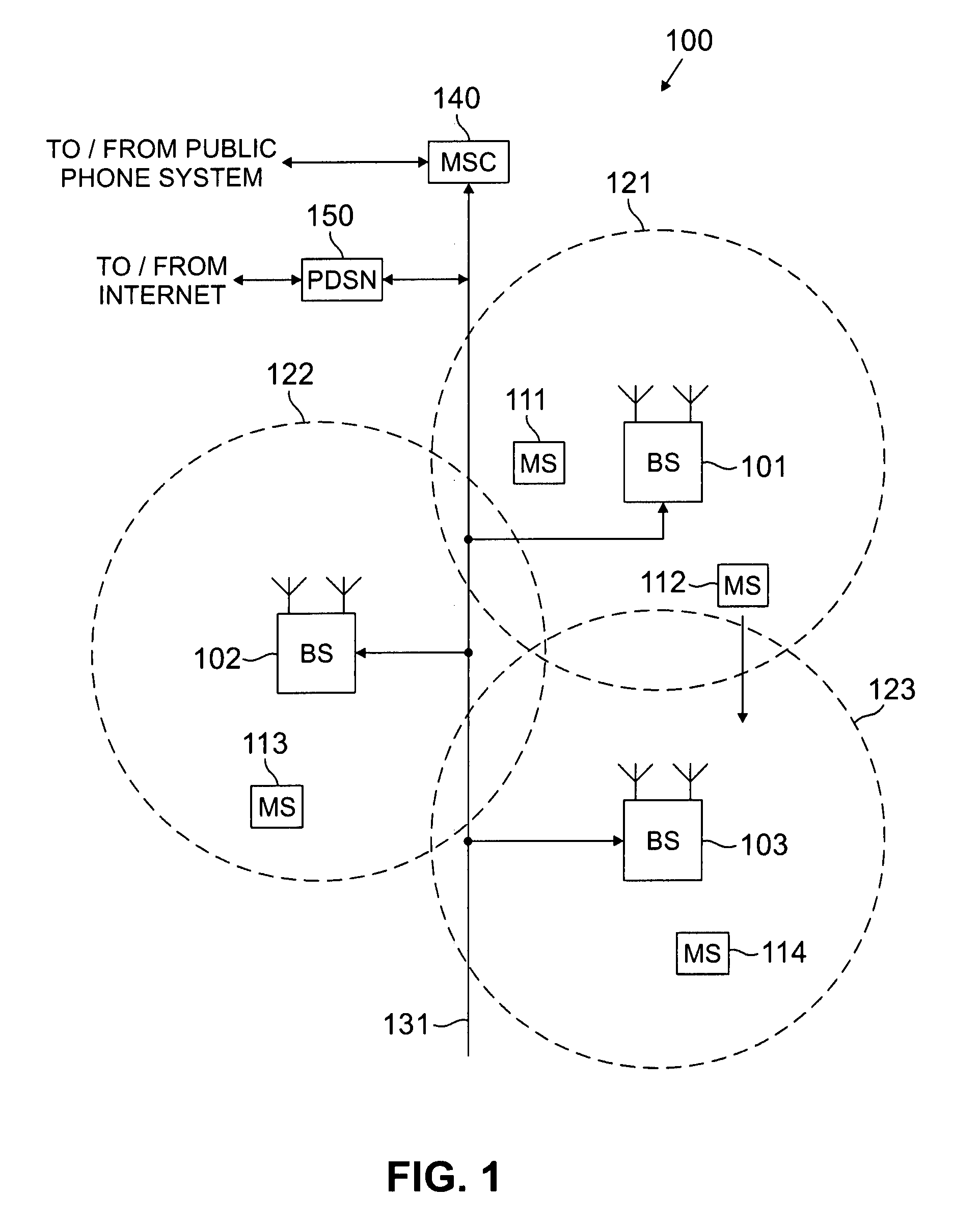
[0028]FIG. 1 illustrates exemplary wireless network 100, in which mobile station RAKE receivers using channel estimation techniques according to the principles of the present invention may be used. Wireless network 100 comprises a plurality of cell sites 121-123, each containing a base station (BS), such as BS 101, BS 102, or BS 103. Base stations 101-103 communicate with a plurality of mobile stations (MS) 111-114 over, for example, code division multiple access (CDMA) channels. Mobile stations 111-114 may be any suitable wireless devices, including conventional cellular ...


PUM


Abstract

In a RAKE receiver capable of detecting and combining a plurality of multipath signals, a controller for managing the assignment of the plurality of multipath signals to fingers of the RAKE receiver. The controller determines a phase difference between a selected multipath signal and a first multipath signal assigned to a first finger of the RAKE receiver and does not assign the selected multipath signal to a second finger of the RAKE receiver unless the phase difference is greater than one-half chip. If the phase difference is less that one-half chip, the controller assigns the stronger of the selected multipath signal and the first multipath signal to the first finger of the RAKE receiver. If the finger power falls below a certain threshold, the finger internal states (viz. channel estimate and delay estimate) are maintained while the output of the finger is not processed. If the finger power exceeds the threshold anytime within a specified time interval, the normal activities of the finger are restored. If the power remains lower than the threshold for that time period, the finger is deactivated.

Description

TECHNICAL FIELD OF THE INVENTION[0001]The present invention relates generally to wireless receivers and, more particularly, to an apparatus and a related method in a wireless receiver that performs finger management in a RAKE receiver.BACKGROUND OF THE INVENTION[0002]Business and consumers use a wide array of wireless devices, including cell phones, wireless local area network (LAN) cards, global positioning system (GPS) devices, electronic organizers equipped with wireless modems, and the like. The increased demand for wireless communication devices has created a corresponding demand for technical improvements to such devices. Generally speaking, wireless system designers attempt to minimize the cost of conventional radio receivers while improving the performance of such devices. Performance improvements include, among other things, lower power consumption, greater range, increased receiver sensitivity, lower bit error rates (BER), higher transmission rates, and the like.[0003]Sign...

Claims


Application Information

Patent Timeline
Patent Type & Authority Patents(United States)
IPC IPC(8): H04B1/00
CPCH04B1/7117
Inventor BANERJEE, DEBARAG N.
Owner NAT SEMICON CORP
Why Eureka
Try Eureka