Biothermal power source for implantable devices

a biothermal power source and implantable device technology, applied in secondary cells, generators/motors, therapy, etc., can solve the problems of radio-frequency rechargeable implanted devices being unable to diagnose potentially serious conditions with mri, the power source itself being used in medical electronics, etc., to increase the thermal gradient and increase the thermal gradient

Inactive Publication Date: 2008-03-04
BIOMED SOLUTIONS
View PDF57 Cites 213 Cited by
  • Summary
  • Abstract
  • Description
  • Claims
  • Application Information

AI Technical Summary

Problems solved by technology

One of the early limitations to the implantation of medical electronics was the power source itself, and much development work has been done over the past forty years to improve the reliability and longevity of battery sources and to reduce the power demands of the pacemaker circuits themselves.
As a result, current pacemaker batteries last several years in many applications.
However, the use of this technique is inconsistent with the use of magnetic resonance imaging (MRI), so patients with a radio-frequency rechargeable implanted device will be unable to have MRI diagnoses of potentially serious conditions.
Additionally, radio-frequency induction often requires a patient to regularly set aside time for the recharging process; this is often inconvenient and frequently causes non-compliance.
Death of the patient may result, and has resulted, from one or more of these phenomena.
This direct use of MRI at the heart often further exacerbates the existing difficulties in using MRI on pacemaker patients.
This and other similar approaches would help resolve the battery life issues discussed above, were it not for this critical issue of MRI diagnoses; the very presence of an element that can accept externally-provided radio frequency energy makes MRI compatibility for this and similar devices impossible.

Method used


Image

  • Biothermal power source for implantable devices
  • Biothermal power source for implantable devices
  • Biothermal power source for implantable devices

Examples


Embodiment Construction

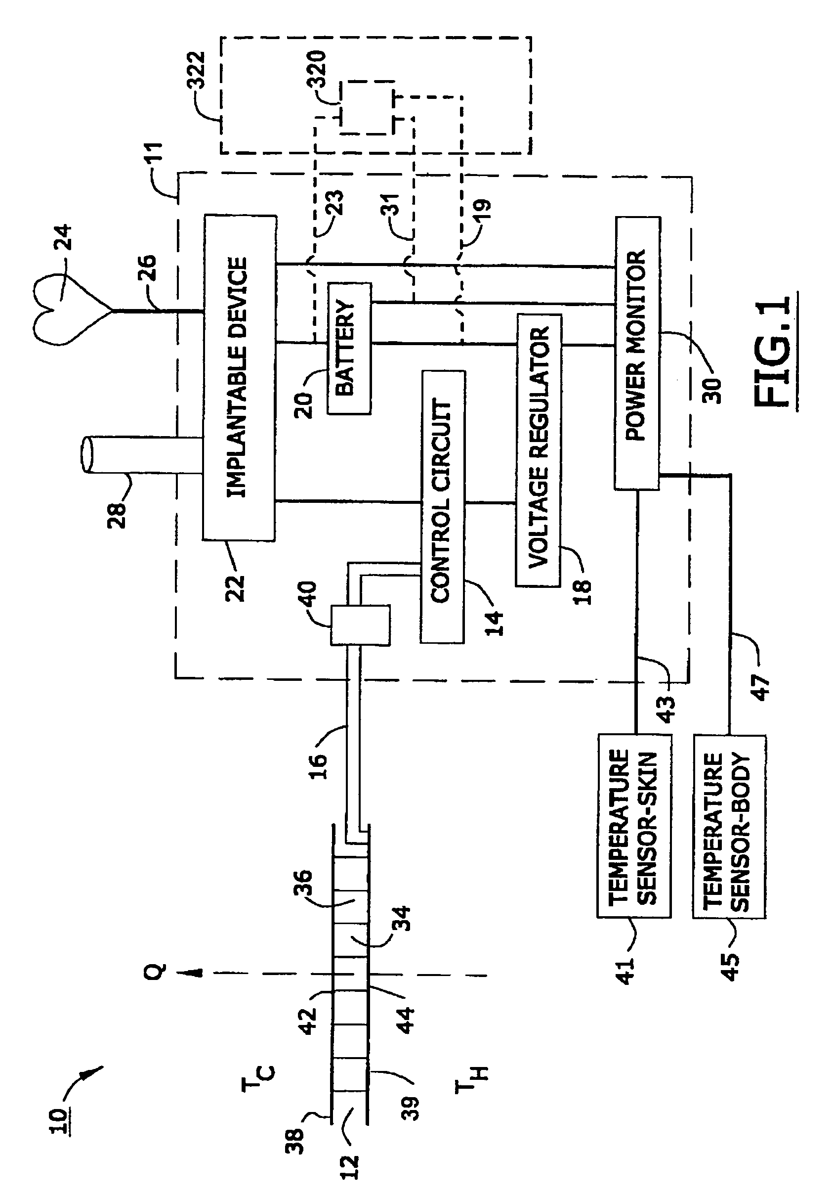
[0032]FIG. 1 is a block diagram of a preferred biothermal power system 10. In the preferred embodiment depicted in FIG. 1, device 10 works on the Seebeck effect.

[0033]The Seebeck effect is the development of a voltage due to differences in temperature between two junctions of dissimilar metals. Reference may be had, e.g., to U.S. Pat. No. 5,565,763 (thermoelectric method and apparatus), U.S. Pat. No. 5,507,879 (sensor using thermoelectric materials), U.S. Pat. No. 4,019,364 (method of testing welds by using the Seebeck effect), U.S. Pat. No. 3,648,152 (Seebeck effect compensation), U.S. Pat. No. 6,207,886 (Skutterudite thermoelectric material), U.S. Pat. Nos. 6,078,183, 5,952,837, 5,869,892, 5,784,401, 5,708,371, 5,491,452 (Peltier element as series noise clamp), U.S. Pat. Nos. 5,446,437, 5,439,528 (laminated thermo element), U.S. Pat. Nos. 5,241,828, 5,073,758, 4,938,244, 4,505,427, 4,095,998 (thermoelectric voltage generator), U.S. Pat. No. 4,026,726, and the like. The entire disc...


PUM

PropertyMeasurementUnit
temperatureaaaaaaaaaa
electrical poweraaaaaaaaaa
thicknessaaaaaaaaaa

Abstract

An implantable, rechargeable assembly comprised of an implantable device disposed within a living organism, an electrical storage device connected to the implantable device, and a thermoelectric charging assembly operatively connected to the electrical storage device. The thermoelectric charging assembly has devices for transferring thermal energy between the living organism and a thermoelectric module, for generating an electrical current from the thermal energy, for charging the electrical storage device with the electrical current, for determining the extent to which the electrical storage device is being charged with the electrical current, and for generating a signal whenever the extent to which the electrical storage device is being charged with the electrical current falls below a specified value.

Description

CROSS-REFERENCE TO RELATED PATENT APPLICATIONS[0001]This application is a continuation of patent application U.S. Ser. No. 10 / 694,548, filed on Oct. 27, 2003, now abandoned which is a continuation-in-part of patent application U.S. Ser. No. 10 / 098,821, filed on Mar. 15, 2002, now U.S. Pat. No. 6,640,137, both of which are incorporated herein by reference.FIELD OF THE INVENTION[0002]A device for providing a permanent source of energy comprised of a thermoelectric module for creating electrical energy created by a temperature gradient in the body.BACKGROUND OF THE INVENTION[0003]Implantable medical devices (such as, for example, cardiac assist devices, drug infusion pumps, and pain management devices) all require electrical power to carry out functions such as pacing the heart, delivering a drug, or stimulating nerves. These devices also require electrical power for basic control functions and for communicating with other devices and with external controllers.[0004]The use of these an...

Claims


Application Information

Patent Timeline
Patent Type & Authority Patents(United States)
IPC IPC(8): A61N1/362A61M5/00A61N1/375A61N1/08A61N1/378H01L35/28H01L35/30H01M10/44
CPCA61N1/08A61N1/3785H01L35/00H02N11/002A61N1/3708A61N1/3718H01M10/42Y02E60/10H10N10/00
Inventor MACDONALD, STUART G.
Owner BIOMED SOLUTIONS
Why Eureka
Try Eureka