
Arbitrary waveform generator with configurable digital signal processing unit

a digital signal processing unit and generator technology, applied in the field of instrumentation systems, can solve the problems of time-consuming software computation, etc., and achieve the effects of less complex, large amount of on-board memory, and large download times

Active Publication Date: 2008-03-04
NATIONAL INSTRUMENTS
View PDF12 Cites 13 Cited by
  • Summary
  • Abstract
  • Description
  • Claims
  • Application Information

AI Technical Summary

Benefits of technology

[0010]Typically, waveforms generated by arbitrary waveform generators need to meet strict frequency or time domain specifications. This can often translate into very complex waveforms that require time-consuming software computation, large amounts of on-board memory, and large download times. Computing these complex waveforms in hardware may alleviate many of the disadvantages of typical arbitrary waveform generators. Performing computations in hardware is usually much faster than software computations. Also, by performing hardware computations, much smaller (less complex) waveforms may need to be saved in the memory since the hardware would compute the complex waveforms during the waveform generation process. Since less memory may be required to store waveform data, memory download times may be significantly reduced.

Problems solved by technology

This can often translate into very complex waveforms that require time-consuming software computation, large amounts of on-board memory, and large download times. Computing these complex waveforms in hardware may alleviate many of the disadvantages of typical arbitrary waveform generators.

Method used


Image

  • Arbitrary waveform generator with configurable digital signal processing unit
  • Arbitrary waveform generator with configurable digital signal processing unit
  • Arbitrary waveform generator with configurable digital signal processing unit

Examples


Embodiment Construction

Waveform Generation System

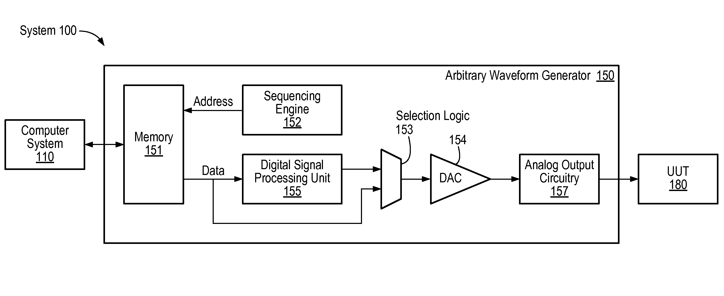
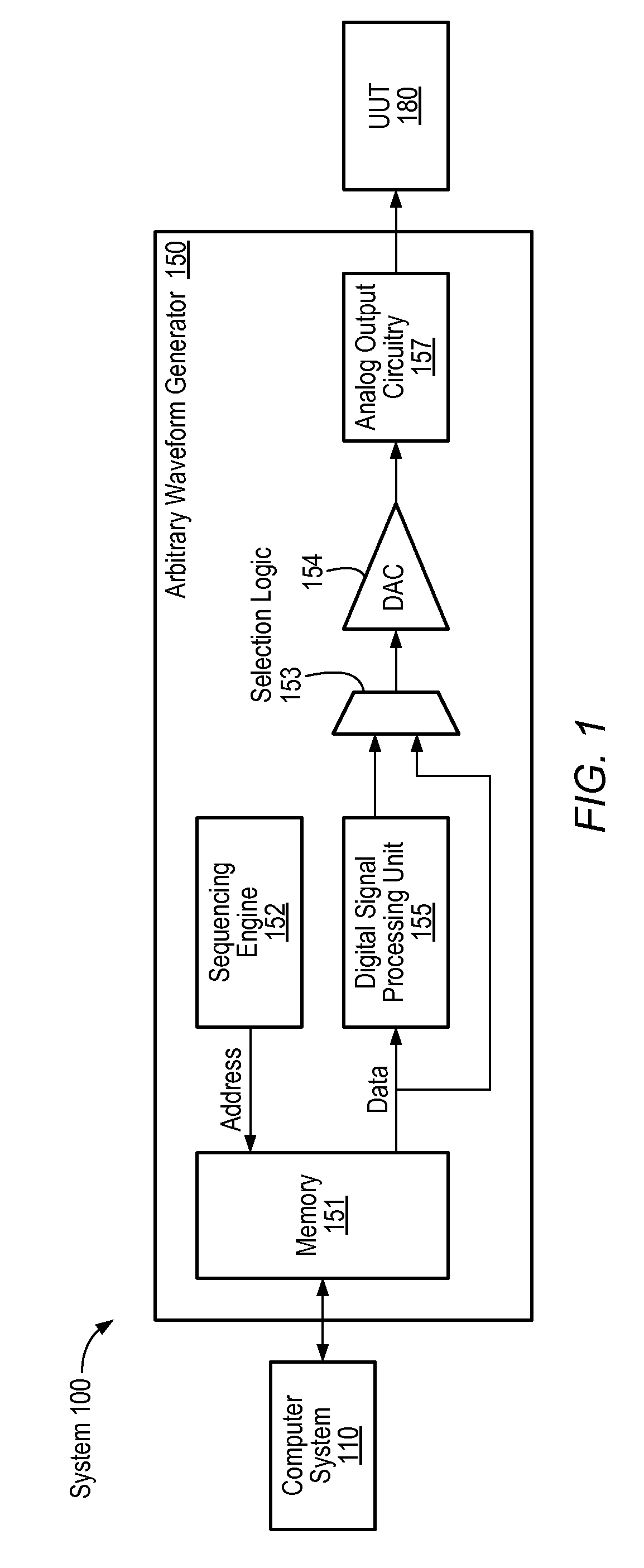
[0018]Turning now to FIG. 1, a block diagram of one embodiment of a waveform generation system 100 is shown. In the illustrated embodiment, the system 100 includes a computer system 110, an arbitrary waveform generator 150, and a unit under test (UUT) 180. The computer system 110 is connected to the arbitrary waveform generator 150, which is further connected to the UUT 180. The computer system 110 may be a personal computer (PC) system. However, it is noted that in other embodiments the computer system 110 may be any of various types of computing or processing systems, including mainframe computer systems, workstations, and portable computers, among others. It is also noted that the components of the system 100 may be interconnected in various ways.

[0019]The arbitrary waveform generator 150 may be a board or card which may be receivable in the computer system 110. It is noted however that in some embodiments the arbitrary waveform generator 150 may be anot...


PUM


Abstract

An arbitrary waveform generator including a digital signal procession unit and a memory. The digital signal processing unit may be configurable to interconnect a plurality of processing components in different configurations to process data received from the memory and perform one of a plurality of different functions to compute or enhance waveforms without having to store complex waveform data in the memory. In a first configuration, the digital signal processing unit may perform digital up-conversion functions on received waveform data to generate enhanced waveform data, and in a second configuration may perform data interpolation functions to generate enhanced waveform data. In a third configuration, the digital signal processing unit may receive data comprising attributes of a waveform from the memory and perform hardware-controlled arbitrary waveform generation functions. In a fourth configuration, the digital signal processing unit may receive information from software and perform software-controlled arbitrary waveform generation functions.

Description

BACKGROUND OF THE INVENTION[0001]1. Field of the Invention[0002]This invention relates to instrumentations systems and, more particularly, to arbitrary waveform generator design.[0003]2. Description of the Related Art[0004]Signal generation is used in a wide variety of applications, including, for example, industrial testing and verification, product design, and control, among others. In one application of signal generation, a signal is generated according to waveform data, and provided as input or stimulus to a unit under test (UUT). Resulting output from the UUT may then be analyzed to characterize the UUT, e.g., for quality control, design feedback, etc. Generally, waveform generators are used to generate such signals.[0005]Waveform generators may be used to produce one or more waveforms having defined characteristics. A waveform is a graphical representation of a signal, for example, an analog data signal or a digital data signal. The graphical representation may be a plot of am...

Claims


Application Information

Patent Timeline
Patent Type & Authority Patents(United States)
IPC IPC(8): G01R13/00
CPCG01R31/2841
Inventor AMMERMAN, JOHNATHAN R. W.BUTLER, CARY PAUL
Owner NATIONAL INSTRUMENTS
Learn More