Dual belt conveyor oven

a conveyor oven and belt conveyor technology, applied in baking ovens, heating types, stoves or ranges, etc., can solve the problems of excess equipment expense, time loss and wastage of oven production capacity, and mechanical complexity

Active Publication Date: 2008-03-11
WOLFE ELECTRIC
View PDF16 Cites 31 Cited by
  • Summary
  • Abstract
  • Description
  • Claims
  • Application Information

AI Technical Summary

Benefits of technology

[0014]In operation of the instant invention, and assuming the provision of a preferred embodiment as described above, and further assuming for the sake of example that it is desirable that a pizzeria maintain five minute and three minute transit times within its dual conveyor oven, the annularly coffered step configuration of the drive roller may effectively present left and right two inch and three and one-third inch diameter drive sprockets which are spaced axially along the roller. Accordingly, where the transit time of a continuous loop grate driven by the three and one-third inch diameter drive sprocket is adjusted to three minutes, the adjacent continuous loop grate will automatically have a five minute transit time. Thus, the single drive axle and speed control of the instant invention may advantageously maintain dual conveyor speeds.

Problems solved by technology

A problem associated with such upward adjustment of the conveyor speed arises when a next successive item to be cooked within the oven comprises a pizza which must be cooked at a slower speed.
The process of adjusting and readjusting a single conveyor's speed in accordance with cooking times needed by various food items results in time loss and wastage of the production capacity of the oven.
Provision of such additional mechanisms and equipment undesirably results in excess mechanical complexity and excess equipment expense.

Method used


Image

  • Dual belt conveyor oven
  • Dual belt conveyor oven
  • Dual belt conveyor oven

Examples


Embodiment Construction

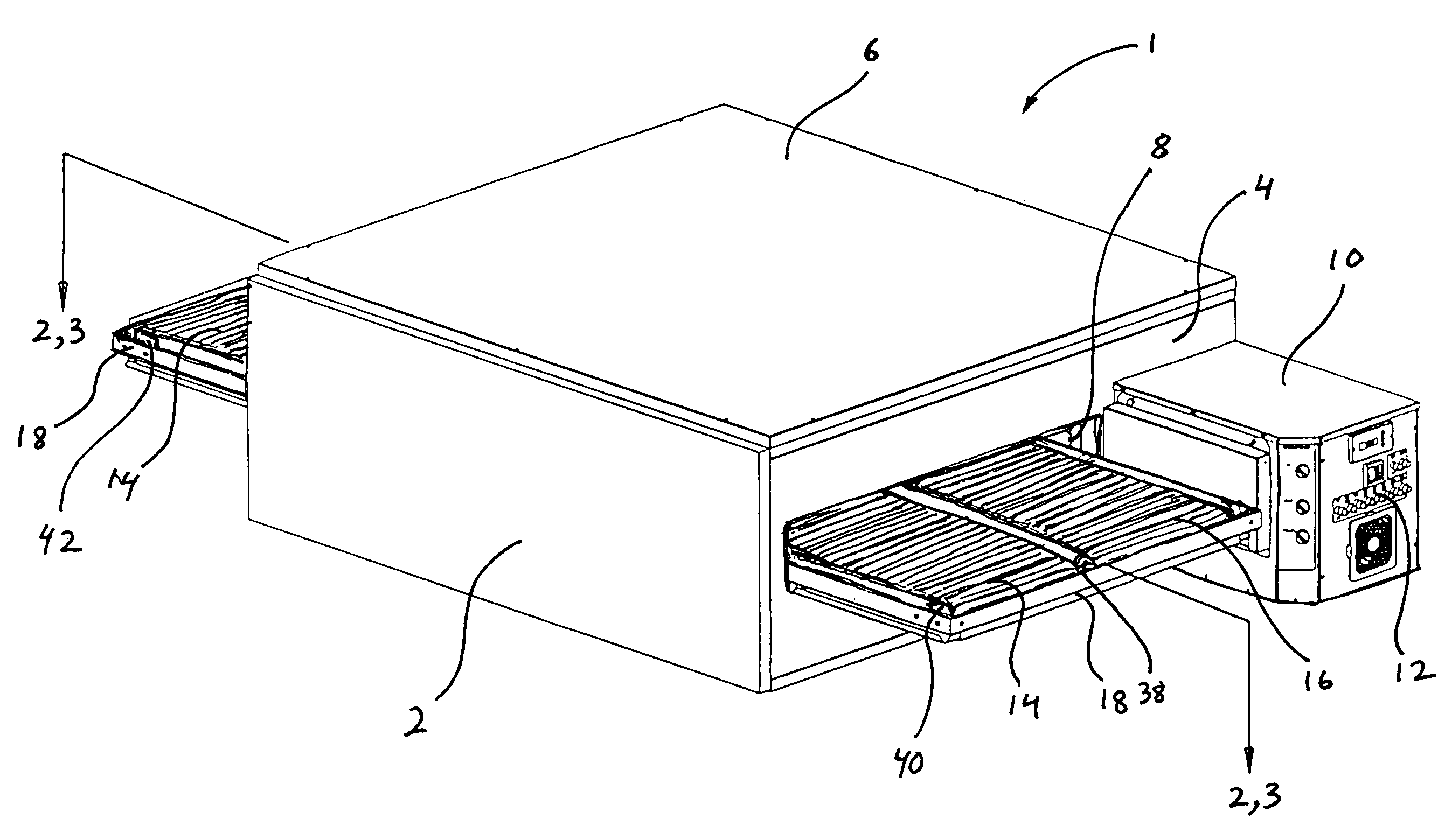
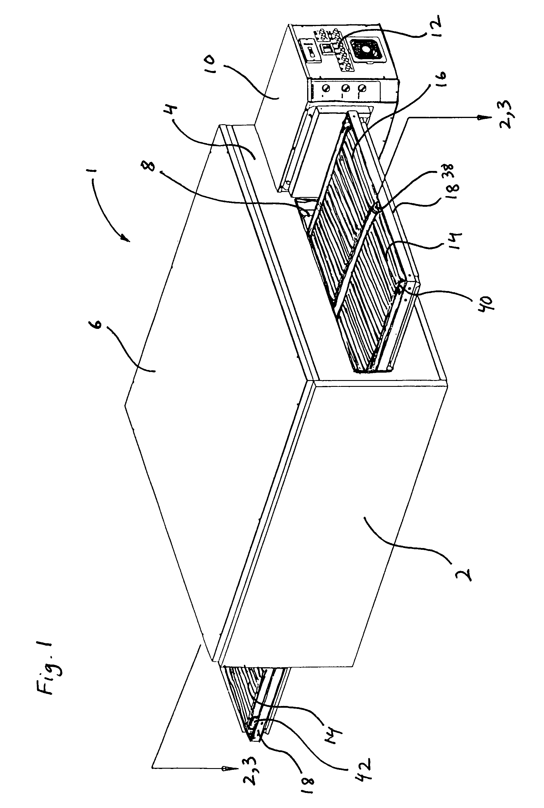
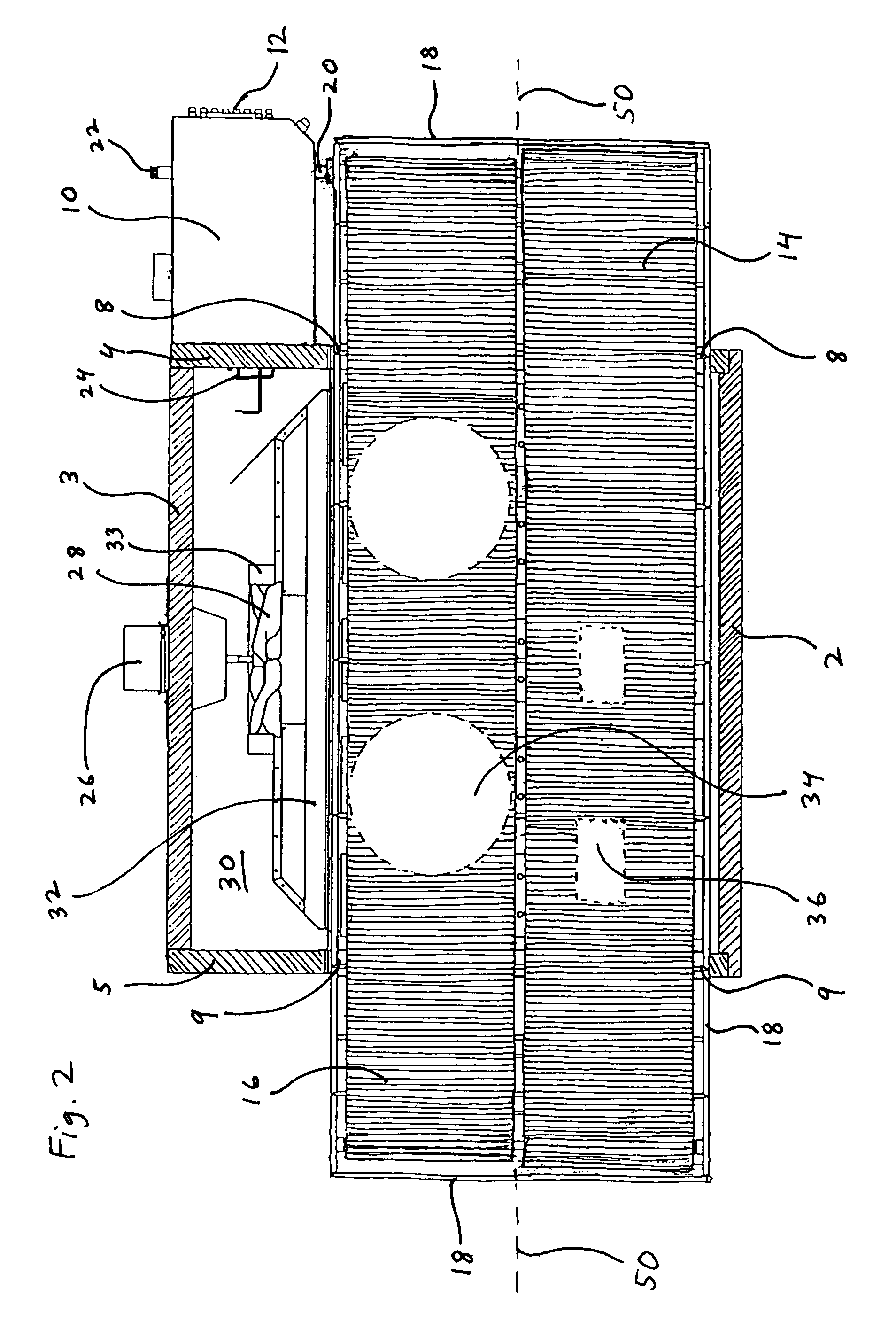
[0021]Referring now to the drawings, and in particular simultaneously to FIGS. 1 and 2, the instant inventive oven 1 preferably comprises a thermally insulated case including front and rear walls 2 and 3, longitudinally spaced end walls 4 and 5, and a top or roof 6 and a floor. Longitudinal end wall 4 has a laterally oblongated food input port 8, and longitudinal end wall 5 similarly has a laterally oblongated food output port 9.

[0022]Referring to FIG. 1, the oven 1 preferably has a wall mounted control box 10, such box presenting operator controls 12. Referring simultaneously to FIG. 2, a gas fired burner 24 is substantially housed within control box, such burner 24 being supplied with combustion fuel via gas line 22. A DC variable speed electric motor (not depicted within view) is also preferably housed within control box 10, such motor having a drive output shaft 20 extending laterally outwardly from control box 10.

[0023]Referring further to FIG. 3, an air plenum 32 supporting a ...


PUM


Abstract

An air impingement conveyor oven including a baking case having an interior space, a food input port, a food output port, and having a longitudinal axis extending from the food input ports to the food output port; an air heating gas burner connected operatively to the baking case for heating air within the interior space; a plurality of air registers mounted within the baking case's interior space, the air registers being positioned longitudinally along the baking case's longitudinal axis; an air blower mounted within the baking case's interior space; a network of air ducts interconnecting the air registers and the air blower; left and right conveyor belts extending along the baking case's longitudinal axis and being respectively positioned leftwardly and rightwardly from the longitudinal axis; a first roller mounted intersectingly across the baking case's longitudinal axis, the first roller being frictionally engaged with the left and right conveyor belts, the first roller being annularly coffered at said axis; and an electric motor connected operatively to the first roller.

Description

FIELD OF THE INVENTION[0001]This invention relates to air impingement food conveying tunnel ovens. More particularly, this invention relates to such ovens which include dual laterally spaced belt conveyors.BACKGROUND OF THE INVENTION[0002]A major item of cooking equipment used and maintained at pizzerias comprises an air impingement tunnel oven having a belt type continuous loop food conveying cooking grate or rack. A common length of baking time for pizzas cooked within such ovens is five minutes. Accordingly, the conveyor motor speed of such an oven is commonly adjusted so that the oven's continuous loop grate longitudinally travels within five minutes a distance equal to the longitudinal length of the oven. Such longitudinal transit time allows a pizza carried into the oven by the conveyor to emerge therefrom and cease cooking at the end of the desired five minutes cooking time.[0003]Many pizzerias cook and serve additional menu items such as oven toasted sandwiches which require...

Claims


Application Information

Patent Timeline
Patent Type & Authority Patents(United States)
IPC IPC(8): A47J37/00
CPCA21B1/245A21B1/48A47J37/045
Inventor WOLFE, GARY L.WOLFE, RONALD D.
Owner WOLFE ELECTRIC
Why Eureka
Try Eureka