Hydraulic fluid plenum plate assembly

a technology of hydraulic fluid and plenum plate, which is applied in the direction of gearing details, transportation and packaging, gearing, etc., can solve the problems enhance their performance and cost, and reduce air bubble entrapment and time delay problems, and achieves easy and inexpensive manufacturing. , the effect of reducing the problem of air bubble entrapment and time delay

Inactive Publication Date: 2008-03-11
DANA AUTOMOTIVE SYST GRP LLC
View PDF14 Cites 22 Cited by
  • Summary
  • Abstract
  • Description
  • Claims
  • Application Information

AI Technical Summary

Benefits of technology

[0009]Such an arrangement of the plenum plate assembly effectively reduces air bubble entrapment and time delay problems, commonly occurred in the prior art, when the hydraulic fluid pump starts generating pressurized hydraulic fluid. Other advantages and novel features of the present invention will become apparent in the following detailed description of the invention when considered in conjunction with the accompanying drawings.

Problems solved by technology

In other words, the prior art plenum chamber arrangement poses the problem of air bubble entrapment and the time delay.
Therefore, the hydraulically actuated torque coupling assemblies of the prior art having plenum chambers, including but not limited to those discussed above, are susceptible to improvements that may enhance their performance and cost.

Method used


Image

  • Hydraulic fluid plenum plate assembly
  • Hydraulic fluid plenum plate assembly
  • Hydraulic fluid plenum plate assembly

Examples


Embodiment Construction

[0018]The preferred embodiment of the present invention will now be described with the reference to accompanying drawings.

[0019]For purposes of the following description, certain terminology is used in the following description for convenience only and is not limiting. The words “right,”“left,”“lower,” and “upper” designate directions in the drawings to which reference is made. The words “uppermost” and “lowermost” refer to position in a vertical direction relative to a geometric center of the apparatus of the present invention and designated parts thereof. The terminology includes the words above specifically mentioned, derivatives thereof and words of similar import. Additionally, the word “a,” as used in the claims, means “at least one.”

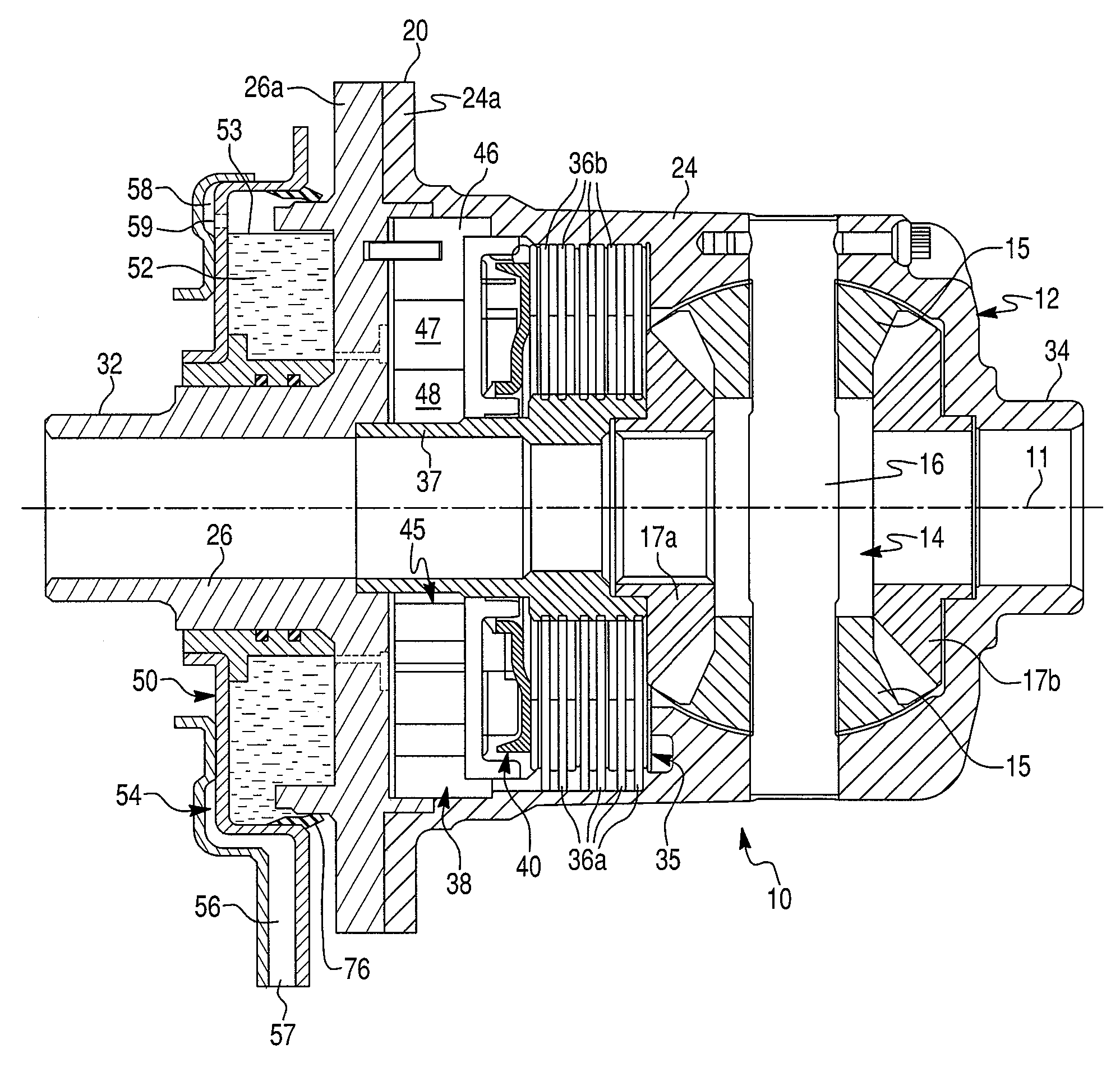
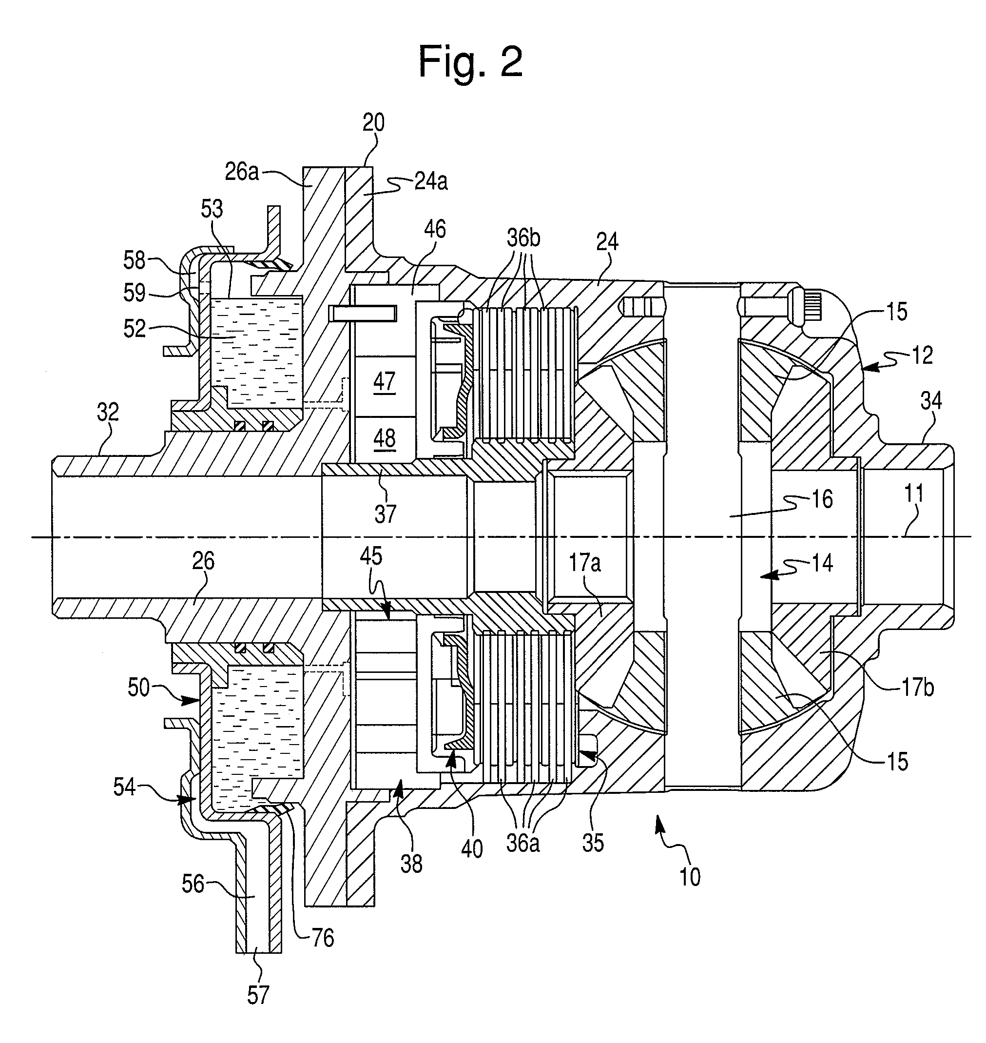
[0020]The present invention is directed to a hydraulically actuated torque coupling assembly including a hydraulic fluid pump, such as a hydraulically controlled limited slip differential (LSD) assembly indicated generally at 10 in FIGS. 2 and 3 t...


PUM


Abstract

A hydraulic fluid plenum plate assembly in a torque-coupling assembly, non-rotatably mounted to a rotatable coupling case thereof so as to form a plenum chamber between the plenum plate assembly and the coupling case. The coupling case has an inlet port fluidly connecting the plenum chamber with a hydraulic pump disposed within the coupling case. The plenum plate assembly comprises a pickup tube for supplying a hydraulic fluid from a fluid reservoir to the plenum chamber. The pickup tube has inlet and outlet ends. The inlet end has an inlet opening submerged in the hydraulic fluid in the fluid reservoir. The outlet end has an outlet opening fluidly connecting the pickup tube with the plenum chamber. The outlet opening is disposed above the inlet port in the coupling case at any angular position of the coupling case relative to the plenum plate assembly.

Description

BACKGROUND OF THE INVENTION[0001]1. Field of the Invention[0002]The present invention relates to torque coupling assemblies in general, and more particularly to a hydraulic fluid plenum plate assembly in a hydraulically actuated torque coupling assembly for providing hydraulic fluid from a hydraulic fluid reservoir to a hydraulic fluid pump of the torque coupling assembly.[0003]2. Description of the Prior Art[0004]Many hydraulically actuated torque coupling assemblies, such as motor vehicle limited slip differentials, employ an internal hydraulic pump to convert the spin speed difference between one of output shafts and a differential case to a hydraulic pressure that actuates a piston actuator, which in turn activates a multi-plate friction clutch assembly. As illustrated in FIG. 1, a pickup tube 110 draws a hydraulic fluid from an axle sump by a vacuum generated by the hydraulic pump and transports the hydraulic fluid to a hydraulic plenum chamber 112 disposed between a plenum pla...

Claims


Application Information

Patent Timeline
Patent Type & Authority Patents(United States)
IPC IPC(8): F16D25/02F16H48/22
CPCF16D43/284F16H48/08F16H48/22F16H48/30F16H48/34F16H57/0483F16H48/32F16H48/40F16H2200/2071
Inventor PARK, JUNGHO
Owner DANA AUTOMOTIVE SYST GRP LLC
Why Eureka
Try Eureka