Capping unit and control method for same, liquid droplet ejection apparatus and device manufacturing method
a liquid droplet ejection and manufacturing method technology, applied in the direction of instruments, coatings, pretreated surfaces, etc., can solve the problems of increasing the viscosity of liquid droplet solvent, consuming liquid droplet solvent needlessly, and nozzle apertures being blocked, etc., to reduce the viscosity of thickened liquid droplet solvent, prolong the ejection time, and reduce the effect of unnecessary consumption
- Summary
- Abstract
- Description
- Claims
- Application Information
AI Technical Summary
Benefits of technology
Problems solved by technology
Method used
Image

Examples
Embodiment Construction
[0054]The capping unit as well as the control method for the capping unit, the liquid droplet ejection apparatus, and the device manufacturing method according to an embodiment of the present invention will now be described in detail with reference made to the drawings.
Liquid Droplet Ejection Apparatus
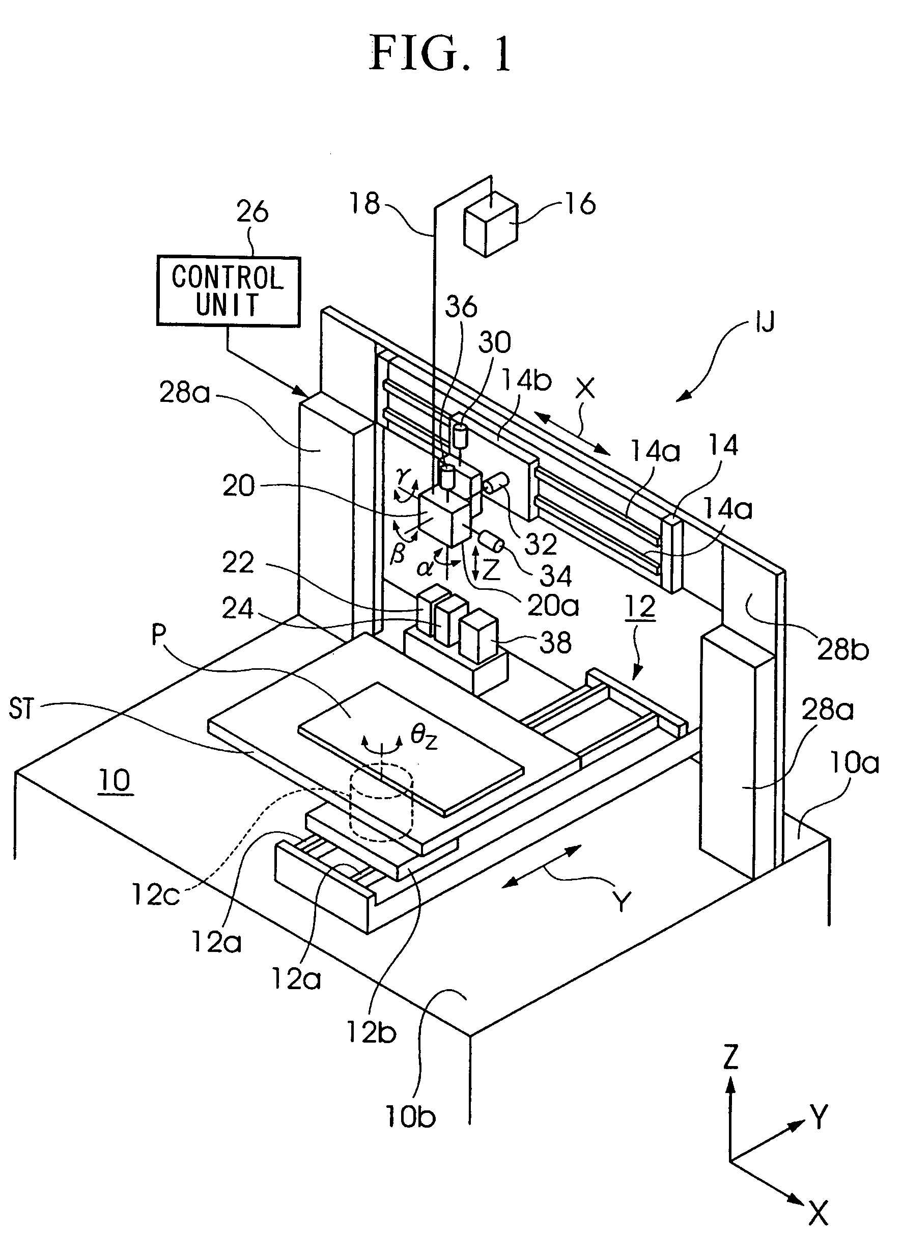
[0055]FIG. 1 is a perspective view showing the schematic structure of a liquid droplet ejection apparatus according to an embodiment of the present invention. Note that, in the description given below, where necessary an XYZ rectangular coordinate system is set in the drawings, and the positional relationship between each member is described with reference made to this XYZ rectangular coordinate system. In the XYZ rectangular coordinate system, the XY plane is set to a plane that is parallel with a horizontal plane, while the Z axis is set to a vertically upright direction. In addition, the direction of movement of the ejection head (i.e., the liquid droplet ejection head) 20 in the pr...
PUM
| Property | Measurement | Unit |
|---|---|---|
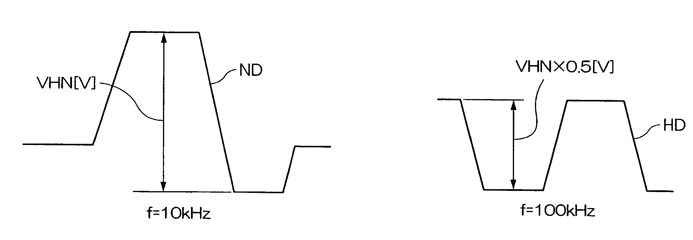
| repetition frequency | aaaaa | aaaaa |
| frequency | aaaaa | aaaaa |
| frequency | aaaaa | aaaaa |
Abstract
Description
Claims
Application Information
 - R&D
- Intellectual Property
- Life Sciences
- Materials
- Tech Scout
- Unparalleled Data Quality
- Higher Quality Content
- 60% Fewer Hallucinations
Browse by: Latest US Patents, China's latest patents, Technical Efficacy Thesaurus, Application Domain, Technology Topic, Popular Technical Reports.
© 2025 PatSnap. All rights reserved.Legal|Privacy policy|Modern Slavery Act Transparency Statement|Sitemap|About US| Contact US: help@patsnap.com