Wideband loop antenna

a loop antenna and wideband technology, applied in the field of antennas, can solve the problems of dipole antennas, difficult to provide small devices with good antenna characteristics, and antenna types, and achieve the effect of high efficiency and low manufacturing cos

Inactive Publication Date: 2008-03-11
SONY CORP
View PDF11 Cites 65 Cited by
  • Summary
  • Abstract
  • Description
  • Claims
  • Application Information

AI Technical Summary

Benefits of technology

[0009]Another problem that the present invention solves is to provide an antenna that is cheap to manufacture.
[0010]One object of the present invention is therefore to provide a wireless communication device, where a small antenna element which only needs a small ground plane for obtaining a certain bandwidth is provided and that provides a high efficiency near the human head.
[0032]Another object of the present invention is to provide an antenna arrangement, which is small and only needs a small ground plane for obtaining a certain bandwidth and that provides a high efficiency near the human head.
[0042]The present invention has many advantages. In addition to providing small antenna size with a small required ground plane, it is cheap to manufacture. In addition to providing good antenna characteristics in a small device, it also provides ESD protection along the sides of the device where the antenna is provided. The present invention furthermore provides good antenna matching. It also does not loose as much efficiency near the head of a user as many other antennas do.

Problems solved by technology

These types of antennas do however have a number of drawbacks when used.
For instance monopole and PIFA antennas need large ground planes, which makes it hard to provide a small device with good antenna characteristics.
A dipole antenna on the other hand needs to be fairly long, which also makes it hard to combine with a small device like a headset.
There is also a significant loss of efficiency in these known devices when used near a human head.
A degradation of the efficiency of ten times has been obtained, which is a serious drawback in relation to headsets.
Another drawback with this antenna is that it is placed above the ground plane, thereby occupying valuable PCB space.

Method used


Image

  • Wideband loop antenna
  • Wideband loop antenna
  • Wideband loop antenna

Examples


Embodiment Construction

[0054]A wireless communication device according to the invention will now be described. It is preferred that the wireless communication device is also portable and small. It is also preferred that the device is a headset, which is a preferred variation of the invention. It is possible to provide it in any other type of small portable communication devices than headsets like hands-free devices, but the invention can equally as well be provided in any other type of portable communication device, like mobile phone or PDA or even a regular computer. The preferred type of device is a device for short length high frequency wireless communication like Bluetooth™.

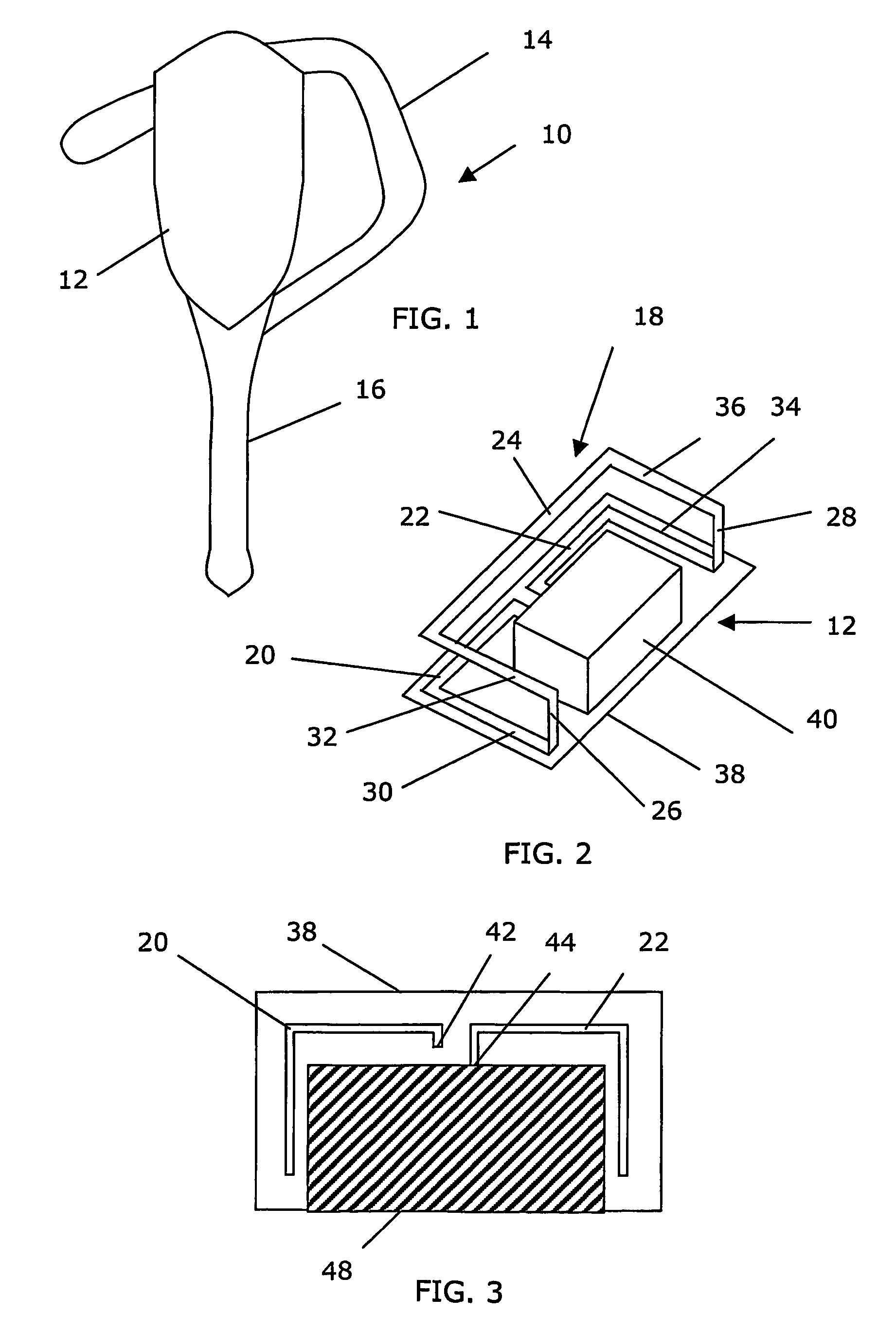
[0055]FIG. 1 shows a schematical drawing of a headset 10 including a main body 12, a microphone part 16 and an ear fastener 14. The main body includes such things as radio circuits working according to the Bluetooth™ protocol, a battery and a speaker, all normal for this type of equipment.

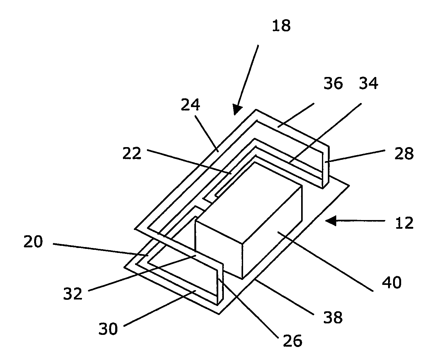
[0056]FIG. 2 shows a perspective view of th...


PUM


Abstract

The present invention relates to a wireless communication device and an antenna arrangement in such a device, where a loop antenna element (18) comprises: a first section (20) provided in and extending a length in first plane, a second section (22) spaced from, provided in and extending a length in the first plane, a third section (24) in a second plane parallel to the first plane, aligned with the first and second sections, and a fourth (26) and a fifth section (28) interconnecting antenna sections in the first and second planes. The sections form a three-dimensional structure having a substantial two-dimensional extension in at least one of the first and second planes. The second section extends along the same line as the first section or has a curvature, which is a continuation of the curvature of the first section. Thereby a small wideband antenna requiring a small ground plane is obtained.

Description

RELATED APPLICATIONS[0001]The present application is a 35 U.S.C. § 371 national phase application of PCT International Application No. PCT / EP2003 / 011532, having an international filing date of Oct. 17, 2003 and claiming priority to European Patent Application No. 02024241.8, filed Oct. 31, 2002, and to U.S. Provisional Application No. 60 / 424,400 filed Nov. 7, 2002, the disclosures of which are incorporated herein by reference in their entireties. The above PCT International Application was published in the English language and has International Publication No. WO 04 / 040697 A1.TECHNICAL FIELD OF THE INVENTION[0002]The present invention relates to the field of antennas and more particularly to a wireless communication device including a loop antenna element as well as to an antenna arrangement for a wireless communication device.DESCRIPTION OF RELATED ART[0003]The antennas within the field of wireless communication devices, especially small such devices like devices to be used for sho...

Claims


Application Information

Patent Timeline
Patent Type & Authority Patents(United States)
IPC IPC(8): H01Q1/24H01Q7/00H01Q9/26
CPCH01Q1/243H01Q7/00H01Q9/26
Inventor ROSENBERG, HANSJIDHAGE, HENRIKSVENSSON, BENGT
Owner SONY CORP
Why Eureka
Try Eureka