Bypass circuit to prevent arcing in a switching device

a switching device and bypass circuit technology, applied in the field of bypass circuits, can solve the problems of increasing affecting the operation of the switch, etc., and achieving the effects of reducing the size and weight of the switching device, and reducing the potential for arcing

Active Publication Date: 2008-03-11
EATON INTELLIGENT POWER LTD
View PDF8 Cites 231 Cited by
  • Summary
  • Abstract
  • Description
  • Claims
  • Application Information

AI Technical Summary

Benefits of technology

[0002]As is known, electromagnetic switching devices are often used to electrically couple a power source to a load such as an electrical motor or the like. The electromagnetic switching device includes both fixed and movable electrical contacts, as well as, an electromagnetic coil. Upon energization of the electromagnetic coil, the movable contact engages the fixed contact so as to electrically couple the power source to the load. When the electromagnetic coil is de-energized, the movable contact disengages from the fixed contact thereby disconnecting the load from the power source. However, as the contacts are separated, current continues to flow therebetween resulting in an arc between the contacts if minimum arc voltages and arc currents are present. Repeated or continued arcing between the contacts interferes with the ability of the contacts to conduct electricity and may cause the surface of the contacts to become eroded, pitted, or develop carbon build-up. Further, in circuits with high voltage sources, elimination of the continued arcing between the contacts may require special contact configurations, arc chutes, vacuum sealed devices or gas back filled devices. These arc-eliminating devices increase the size and weight of the switching devices. Hence, it is highly desirable to minimize or eliminate the potential for arcing between the contacts of a switching device without resorting to use of these arc-eliminating devices.
[0003]Various devices have been developed to minimize the arcing that may occur between the contacts of a switching apparatus such as an electromechanical switching device. By way of example, Kawate et al., U.S. Pat. No. 5,536,980 discloses a high voltage, high current switching apparatus that incorporates various protector devices that are used in the event of a circuit malfunction. The switching apparatus incorporates a single pole, double throw switching device and a solid state power switch. When the coil of the switching device is energized, the contact arm of the switching device moves into engagement with a first load contact that is operatively connected to a load. When the coil is de-energized, the contact arm of the switching device moves into contact with a second contact which is operatively connected to the gate of an IGBT switch. The collector of the IGBT switch is interconnected to the first load contact. Upon energization of the coil switching device, the movable contact moves toward the first load contact and the switch is turned on. Since the time required for the movable contact to move from the second contact to the first load contact is much greater than the switch turn-on time, the switch will be on prior to engagement of the movable contact with the first load contact. As a result, arcing between the movable contact and the first load contact is eliminated.

Problems solved by technology

However, as the contacts are separated, current continues to flow therebetween resulting in an arc between the contacts if minimum arc voltages and arc currents are present.
Repeated or continued arcing between the contacts interferes with the ability of the contacts to conduct electricity and may cause the surface of the contacts to become eroded, pitted, or develop carbon build-up.
These arc-eliminating devices increase the size and weight of the switching devices.
While the switching apparatus disclosed in the Kawate et al., '980 patent minimizes the arcing between the contacts of a switching device during switching, the circuit disclosed therein has certain inherent problems.
As such, the load may remain hot after the switching process thereby resulting in a potential of shock hazard from the load for a user.
As a result, the circuit disclosed in the Kawate et al., '980 patent dissipates a significant amount of heat and utilizes a significant amount of power.

Method used


Image

  • Bypass circuit to prevent arcing in a switching device
  • Bypass circuit to prevent arcing in a switching device
  • Bypass circuit to prevent arcing in a switching device

Examples


Embodiment Construction

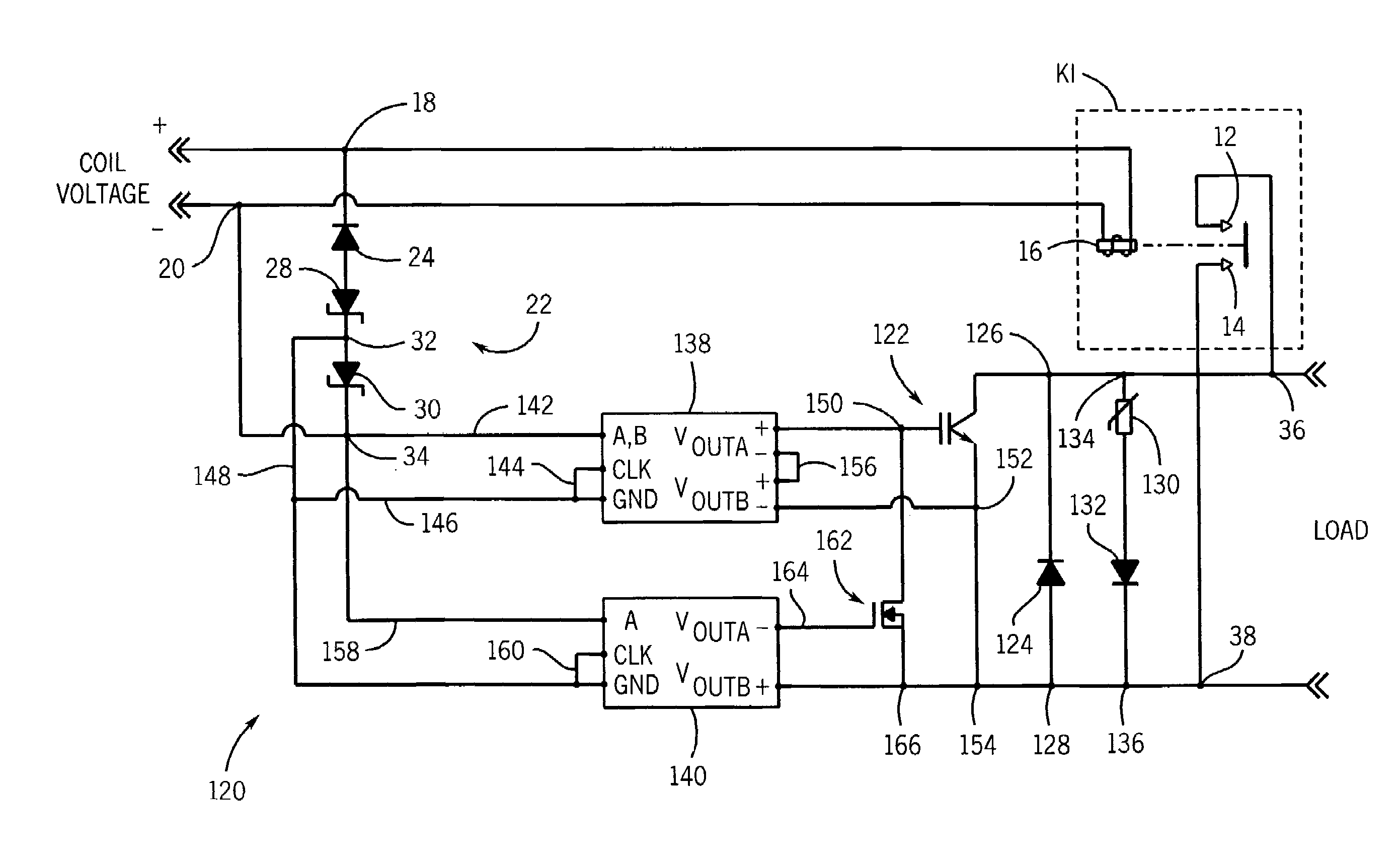
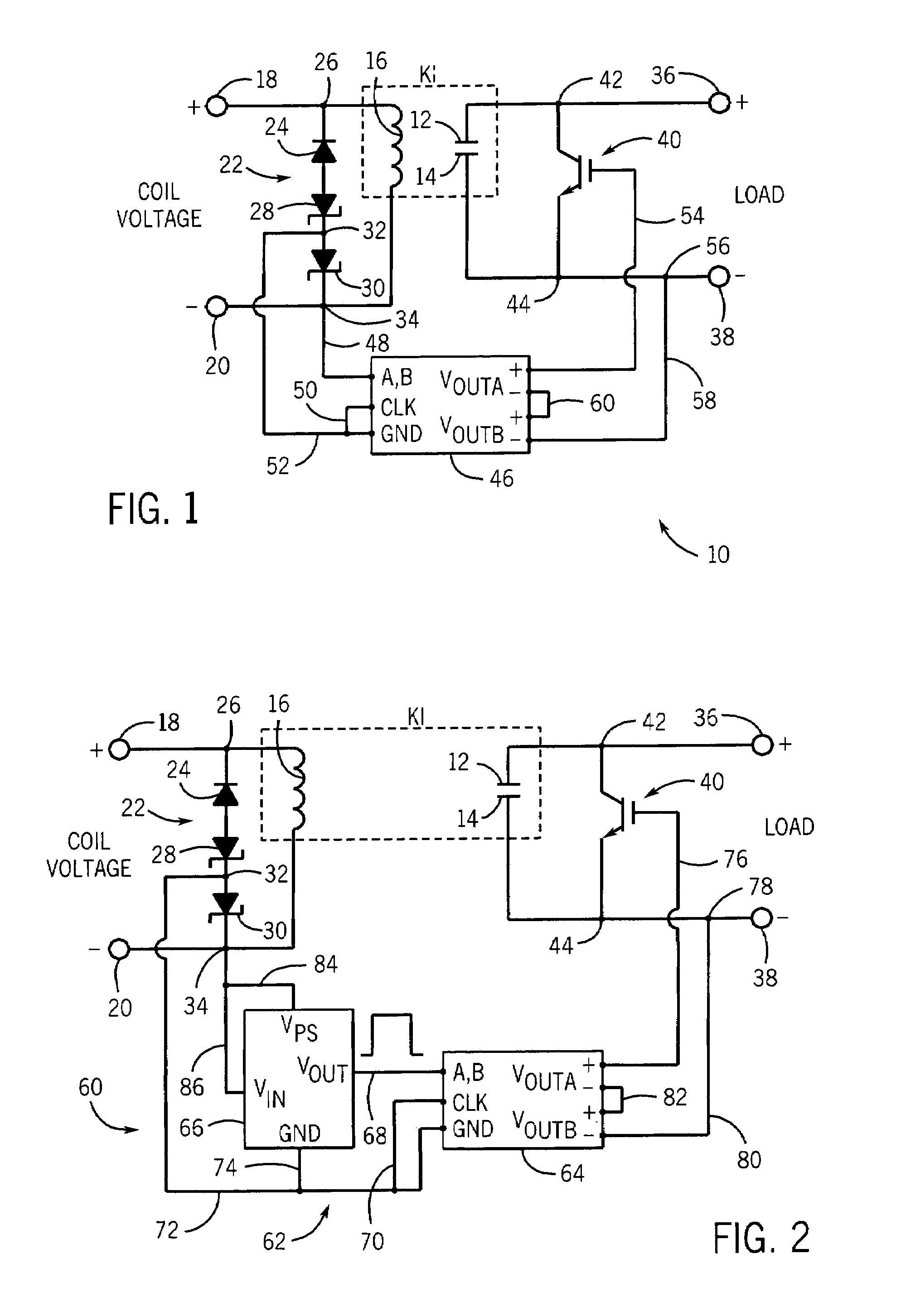
[0028]Referring to FIG. 1, a bypass circuit in accordance with the present invention is generally designated by the reference numeral 10. It is intended that bypass circuit 10 minimize the arcing that may occur during the opening of contacts 12 and 14 of switching device K1 having electrical energy passing therethrough. As is conventional, switching device K1 includes coil 16 that controls the opening and closing of contacts 12 and 14. The first end of coil 16 is connected to positive terminal 18 of a coil voltage source and the second end of coil 16 is connected to negative terminal 20 of the coil voltage source.

[0029]A coil suppression circuit, generally designated by the reference numeral 22, is connected in parallel with coil 16. Coil suppression circuit 22 includes diode 24 having its cathode connected to positive terminal 18 of the coil voltage source at node 26 and its anode connected to the anode of zener diode 28. The cathode of zener diode 28 is connected to the anode of z...


PUM


Abstract

A device is provided for preventing arcing between contacts of a switching device as the contacts of the switching device are opened. The device includes a coil suppression circuit connected in parallel with the coil. The coil suppression circuit dissipates the energy stored in the coil in response to the de-energization of the coil. A first solid state switch has a gate operatively connected to the coil suppression circuit and is connected in parallel with the contacts. The first solid state switch is movable between an open position preventing the flow of current therethrough and a closed position in response to the dissipation of energy by the coil suppression circuit.

Description

FIELD OF THE INVENTION[0001]This invention relates generally to switching devices, and in particular, to a bypass circuit that eliminates the arcing between the contacts of a switching device when the contacts are open.BACKGROUND AND SUMMARY OF THE INVENTION[0002]As is known, electromagnetic switching devices are often used to electrically couple a power source to a load such as an electrical motor or the like. The electromagnetic switching device includes both fixed and movable electrical contacts, as well as, an electromagnetic coil. Upon energization of the electromagnetic coil, the movable contact engages the fixed contact so as to electrically couple the power source to the load. When the electromagnetic coil is de-energized, the movable contact disengages from the fixed contact thereby disconnecting the load from the power source. However, as the contacts are separated, current continues to flow therebetween resulting in an arc between the contacts if minimum arc voltages and ...

Claims


Application Information

Patent Timeline
Patent Type & Authority Patents(United States)
IPC IPC(8): H01H9/30H01H67/02
CPCH01H9/542
Inventor FITZGERALD, LEGAL REPRESENTATIVE, ROBINSANDE, SEAN TILLMANELLSWORTH, MURRAY ROBERTFITZGERALD, EDWARD ALOYSIUS
Owner EATON INTELLIGENT POWER LTD
Why Eureka
Try Eureka