Switch mode power supply systems

a power supply system and switch mode technology, applied in power supply testing, process and machine control, instruments, etc., can solve the problem of additional secondary side components costing more, and achieve the effect of increasing the effective value of said resistive componen

Inactive Publication Date: 2008-03-11
POWER INTEGRATIONS INC
View PDF63 Cites 24 Cited by
  • Summary
  • Abstract
  • Description
  • Claims
  • Application Information

AI Technical Summary

Benefits of technology

[0010]In embodiments of the module which employ one or more low-pass filters the time constant or time constants of the low-pass filters are preferably greater, for example ten times greater than the period over which the filter is averaging. Thus the low-pass filter averaging the primary side charging current should preferably have a time constant which is greater than the on time of the switch drive signal, and the time constant of a low-pass filter implementing the multiplier function should be greater than the (maximum) total cycle time of the SMPS. Therefore, in some preferred embodiments, one or both of these low-pass filters may be implemented using a switched capacitor circuit. In some particularly preferred embodiments one or both of these low-pass filters include a time-sliced resistive component to, effectively, make a resistor of the low-pass filter appear to have a larger value than in fact it has. This facilitates achieving the desirable length of time constant for a low-pass filter in this circuit.
[0012]The invention further provides an SMPS controller including an output current estimating module as described above. In preferred embodiments the controller includes a control module to compare the estimated output current with a target or reference output current, for controlling the SMP responsive to a difference between these two values. The SMPS may, for example comprise an oscillator driving the power switching device, and the controller may control either or both of a pulse width and a pulse frequency of the oscillator. In some preferred embodiments the control module has a zero which is configured to suppress a pole of the output current estimating module, more particularly a pole of a low-pass filter in the estimating module. In embodiments this helps to simply the control loop and hence facilitates achieving improved SMPS control.
[0021]This aspect of the invention also provides a method of implementing a switched capacitor resistor, the method comprising including at least one resistive component in said switched capacitor resistor and time-slicing said resistive component using a time-slicing signal having a duty cycle of less than 100% on time, to increase an effective value of said resistive component.

Problems solved by technology

This provides an accurate method of current sensing but incurs the cost of additional secondary side components.

Method used


Image

  • Switch mode power supply systems
  • Switch mode power supply systems
  • Switch mode power supply systems

Examples


Embodiment Construction

[0037]Broadly speaking we will describe techniques for estimating current on the secondary side of a transformer in a switched mode power supply (SMPS) using low-pass filters. The techniques we describe average the primary-side current twice in two time dominions, the discharge-time (on the secondary-side) and the charge-time (on the primary-side).

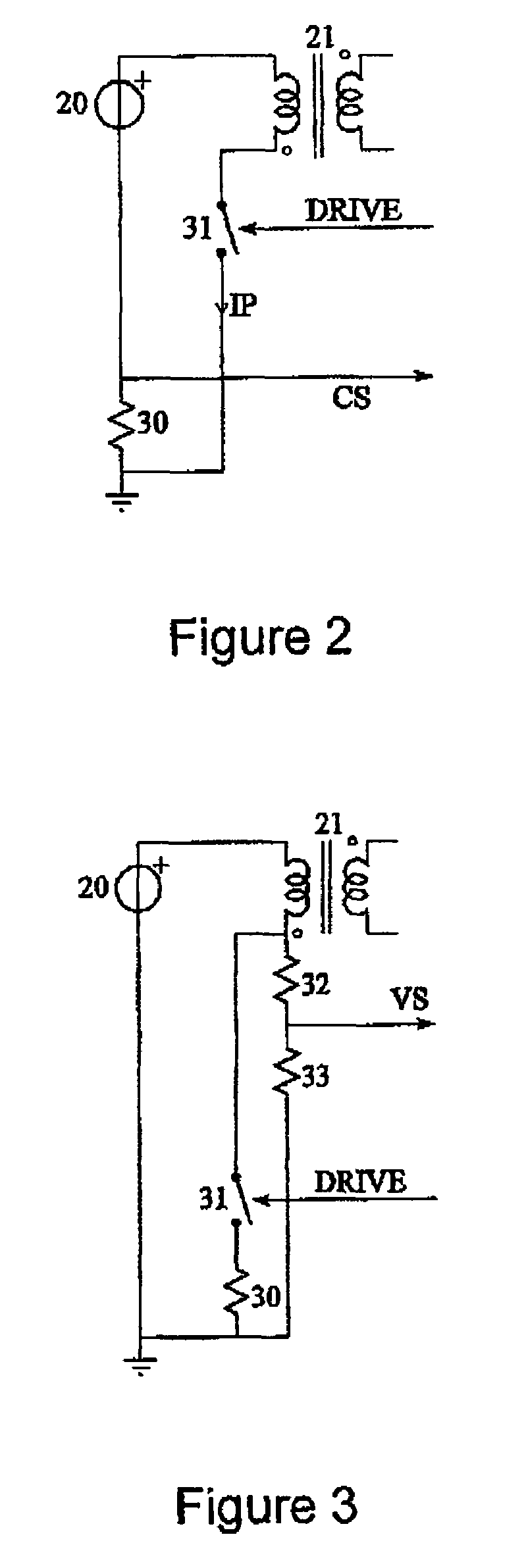
[0038]In embodiments the drive signal for the power switch is used for sensing the charge-time, the current time on the primary-side is used for sensing the average of the primary current and the reflected voltage from the secondary winding is used for sensing the discharge time on the secondary-side. The low-pass filters are implemented using a modified switched-capacitor scheme to reduce the overall size of the passive components in an embodiment.

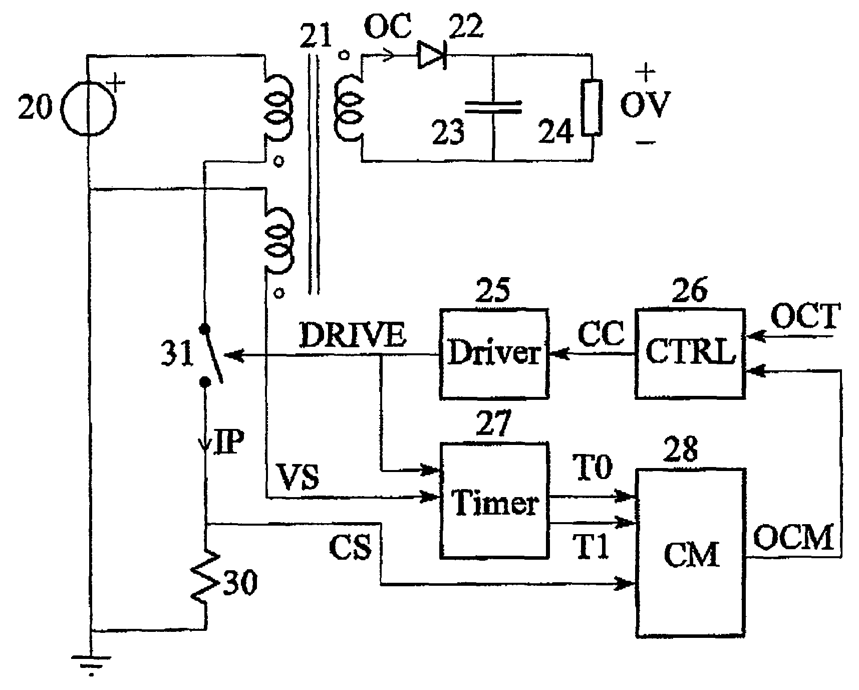
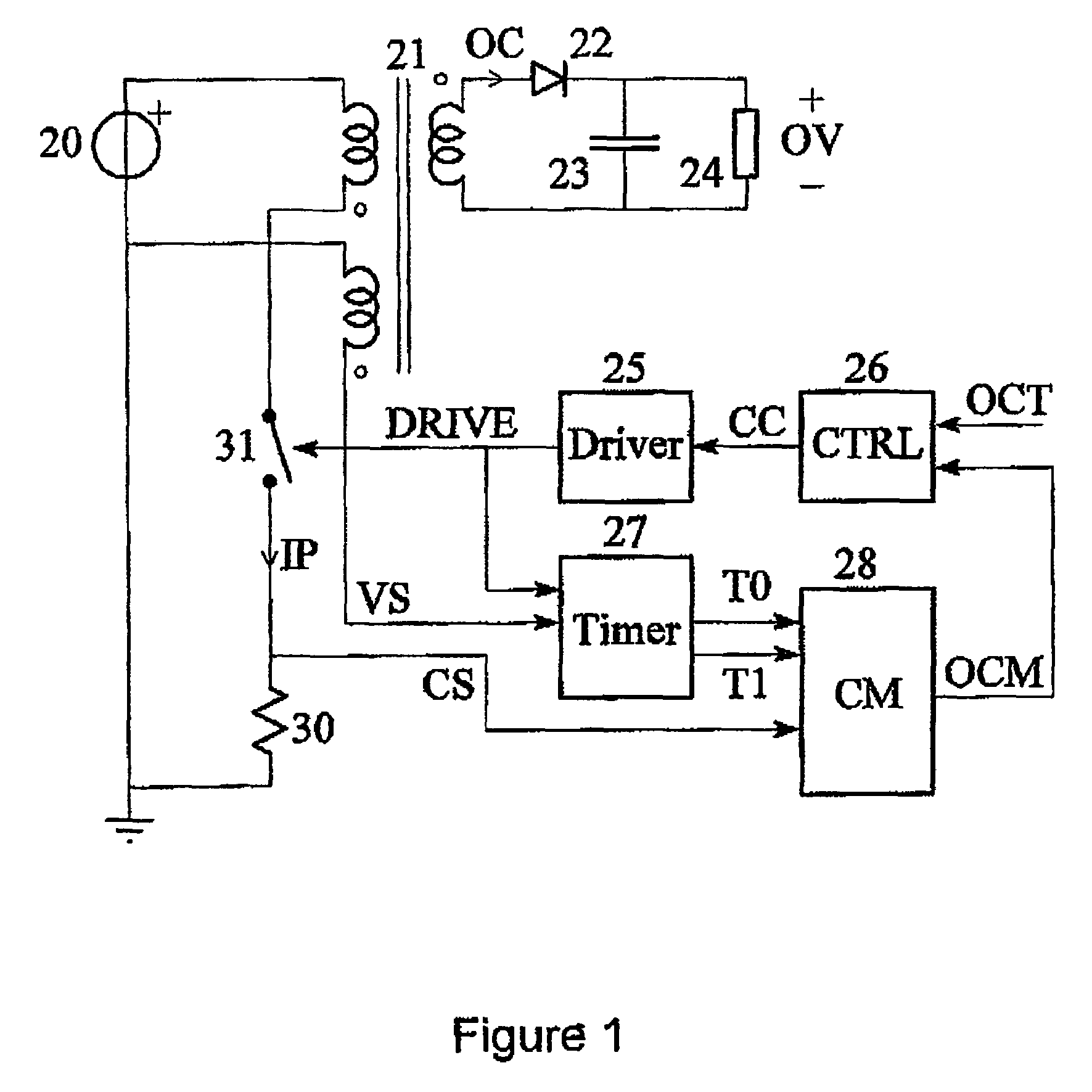
[0039]Referring to FIG. 1 this shows a simplified block diagram of a typical single-switch flyback SMPS. A DC source 20 is connected to the primary winding of a transformer 21 in series with a p...


PUM


Abstract

Methods and apparatus for sensing the output current in a switch mode power supply (SMPS) using primary side sensing are described. A module senses a current in a primary winding of a transformer and a voltage on a primary or auxiliary winding of the transformer, and which includes a multiplier coupled to an output of a signal averager averaging a primary winding current and to an output of a timing signal generator using the sensed voltage to signal when a secondary winding is powering an output of the SMPS, to multiply an averaged current sense signal by a fraction of a total cycle period of said SMPS during which the secondary winding is providing power to provide a signal estimating an output current of the SMPS.

Description

RELATED APPLICATION[0001]This application claims priority under 35 U.S.C. 119 from United Kingdom Application No. 0613484.5 filed 7 Jul. 2006, which application is incorporated herein by reference.FIELD OF THE INVENTION[0002]This invention generally relates to methods and apparatus for sensing the output current in a switch mode power supply (SMPS), in particular using primary side sensing.BACKGROUND TO THE INVENTION[0003]We will describe improved techniques which enable the design of a Switch Mode Power Supply with a relatively accurately controlled output current limit which, in embodiments, do not need current sensing components on the secondary side of the power supply.[0004]Many SMPS applications require the output current to be either limited to, or maintained at a particular value. One way of achieving this is by including some form of output current sensing, located on the secondary side of the converter, communicating this information back to the power converter controller ...

Claims


Application Information

Patent Timeline
Patent Type & Authority Patents(United States)
IPC IPC(8): H02M3/335H02M7/5395
CPCH02M3/33523H02M2001/0009H02M1/0009G01R19/003G01R31/40H03H19/004
Inventor PIPER, JOHANGARNER, DAVID M.COULSON, DAVID ROBERT
Owner POWER INTEGRATIONS INC
Why Eureka
Try Eureka