Laser scanning device

a laser scanning and laser technology, applied in the direction of instruments, optical elements, discharge tubes/lamp details, etc., can solve the problems of detector stopping the laser driver from operating, the connection between the reference voltage generator and the external device,

Inactive Publication Date: 2008-03-11
ASAHI KOGAKU KOGYO KK
View PDF14 Cites 3 Cited by
  • Summary
  • Abstract
  • Description
  • Claims
  • Application Information

AI Technical Summary

Benefits of technology

[0014]A laser scanning device according to an aspect of the invention includes a semiconductor laser that emits a laser beam, a laser power detector that detects laser beam power of the semiconductor laser, a reference voltage generator that generates reference voltage for controlling the laser beam power of the semiconductor laser in accordance with a laser power control signal provided from an external device, and a laser driver that compares the reference voltage generated by the reference voltage generator and the laser beam power detected by the laser power detector to control a driving current supplied to the semiconductor laser for emitting the laser beam. The laser scanning device further includes an abnormal condition detector that detects the laser power control signal received by the reference voltage generator. When the detected laser power control signal differs from a predetermined signal, which indicates that the connection between the reference voltage generator and the external device is poor, the abnormal condition detector stops the laser driver from operating. Accordingly, the laser scanning device does not emit the laser beam when it is poorly connected to the external device, and there is no danger that the power of the laser beam is adjusted improperly based on the laser power control signal that is erroneously received by the laser scanning device.

Problems solved by technology

When the detected laser power control signal differs from a predetermined signal, which indicates that the connection between the reference voltage generator and the external device is poor, the abnormal condition detector stops the laser driver from operating.

Method used


Image

  • Laser scanning device
  • Laser scanning device
  • Laser scanning device

Examples


Embodiment Construction

[0031]Hereinafter, an embodiment of the present invention will be described with reference to the accompanying drawings.

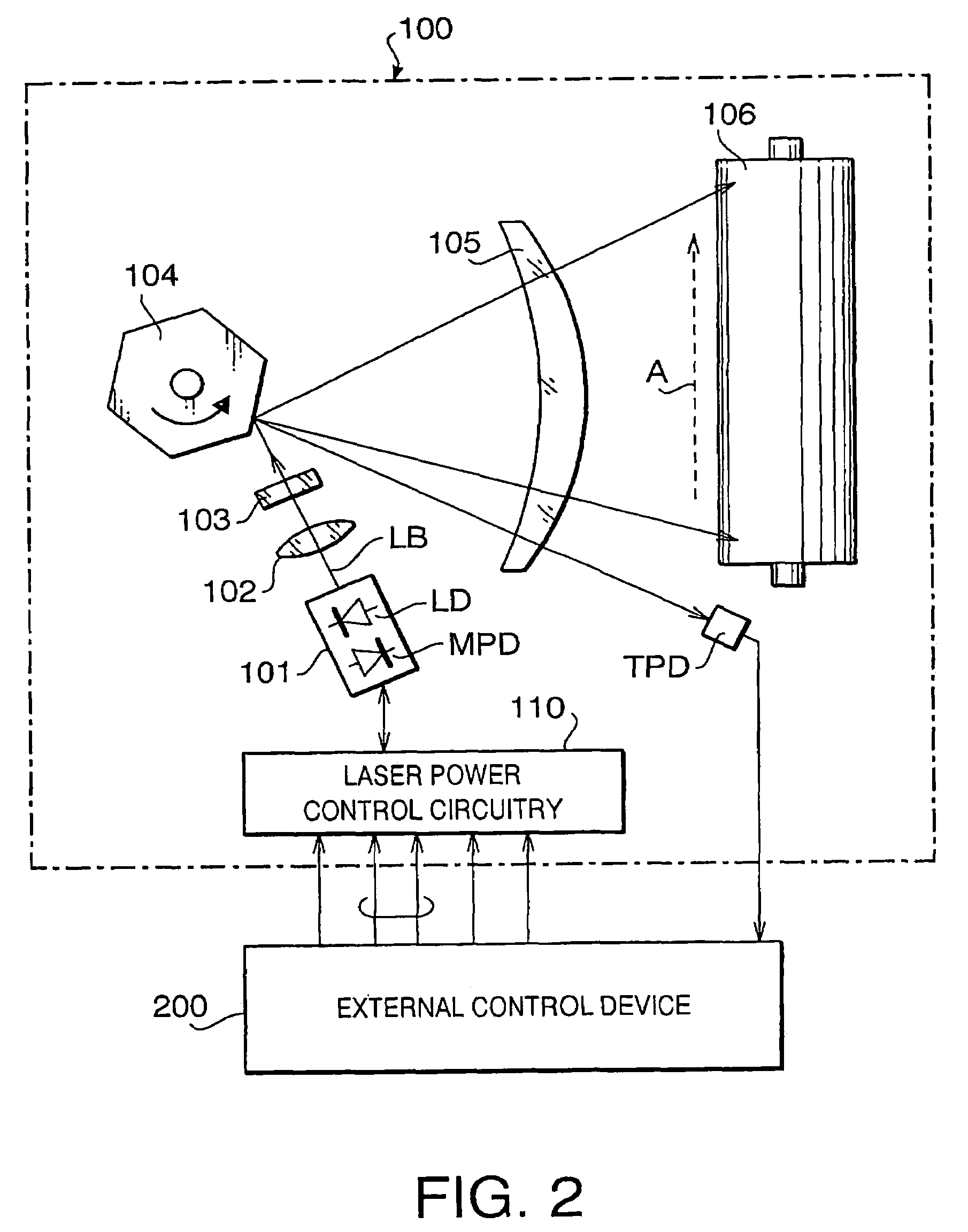
[0032]FIG. 2 schematically shows a configuration of a laser scanning device 100 according to an embodiment of the invention. The laser scanning device 100 is provided with a semiconductor laser LD, a collimator lens 102, a cylindrical lens 103, a polygonal mirror 104, an fθ lens system 105, and a photoconductive drum 106. A laser beam emitted from the semiconductor laser LD is collimated by the collimator lens 102 and then converged only in an auxiliary scanning direction, which is a direction parallel to a rotation axis of the polygon mirror 104. The converged laser beam is further deflected by the polygonal mirror 104 so as to pass through the fθ lens system 105 and scan on the photoconductive drum 106 in a main scanning direction, which is indicated by an arrow A. Note that the fθ lens system 105 is designed so that the laser beam passed therethrough scans on th...


PUM


Abstract

A laser scanning device includes a semiconductor laser that emits a laser beam, a laser power detector that detects laser beam power of the semiconductor laser, a reference voltage generator that generates reference voltage for controlling the laser beam power of the semiconductor laser in accordance with a laser power control signal provided from an external device, and a laser driver that compares the reference voltage generated by the reference voltage generator and the laser beam power detected by the laser power detector to control a driving current supplied to the semiconductor laser for emitting the laser beam. The laser scanning device further includes an abnormal condition detector that detects the laser power control signal received by the reference voltage generator. When the detected laser power control signal differs from a predetermined signal, which indicates that the connection between the reference voltage generator and the external device is poor, the abnormal condition detector stops the laser driver from operating.

Description

BACKGROUND OF THE INVENTION[0001]The present invention relates to a laser scanning device that forms images by scanning a laser beam, and more particularly to a laser scanning device of which laser beam power is adjustable.[0002]A laser scanning device forms an image on a photo-conductive drum by scanning thereon a laser beam that is emitted from a laser source such as a semiconductor laser. If a gray-scale black and white image or a color image is to be produced, the laser scanning device is required to control the power of the laser beam in accordance with the shades of gray or the color to be printed. In order to achieve the above, the laser scanning device is provided with a laser power control circuitry which controls the power of the laser beam in accordance with a laser power control signal provided from an external device.[0003]FIG. 1 is a block diagram of an exemplary laser power control circuitry 1000 utilized in a conventional laser scanning device. The laser power contro...

Claims


Application Information

Patent Timeline
Patent Type & Authority Patents(United States)
IPC IPC(8): H01S3/13B41J2/435H01S3/00B41J2/44G02B26/10G02B26/12H01J3/14H04N1/40
CPCG02B26/127H04N1/40037
Inventor SUDA, TADAAKI
Owner ASAHI KOGAKU KOGYO KK
Why Eureka
Try Eureka