Automatic detector selection by study type

a detector and study type technology, applied in the field of xray systems, can solve the problems of time-consuming, patient potentially being exposed to more radiation than, and users are struggling to efficiently use this type of system, and achieve the effect of less tim

Inactive Publication Date: 2008-03-11
GENERAL ELECTRIC CO
View PDF3 Cites 15 Cited by
  • Summary
  • Abstract
  • Description
  • Claims
  • Application Information

AI Technical Summary

Benefits of technology

[0006]It is therefore an object of the present invention to provide an automated X-ray system including various sized wireless digital detectors. The hardware required includes a computer system and a bank of various sized detectors that are in wireless communication with the computer system. The present invention provides a more efficient X-ray system than known systems. It is more efficient by providing a system that requires less time to determine which detector to use for an ordered X-ray, automatically transmitting the results to the computer system, and automatically pairing the results of the X-ray with any ongoing studies analyzing the captured data.

Problems solved by technology

One disadvantage of this system resulted in the patient potentially being exposed to more radiation than necessary during any given X-ray since the size of the detector could not be changed.
Yet another disadvantage of this type of system is that the film needed to be processed to be useful which resulted in a time consuming endeavor.
This technology is still in its infancy, so users are struggling with how to efficiently use this type of system both from a hardware perspective and an information processing perspective.
While it is advantageous to have flexibility in the size detector used for any given X-ray, a disadvantage of this type of wireless system is that it is time consuming for the X-ray technician to evaluate the type of X-ray being taken, determine which detector is the optimal size to use, and which detector is charged and available for use.
Additionally, it is time consuming to identify studies that are being performed for particular types of X-ray data obtained and associate the obtained data with the identified studies.

Method used


Image

  • Automatic detector selection by study type
  • Automatic detector selection by study type
  • Automatic detector selection by study type

Examples


Embodiment Construction

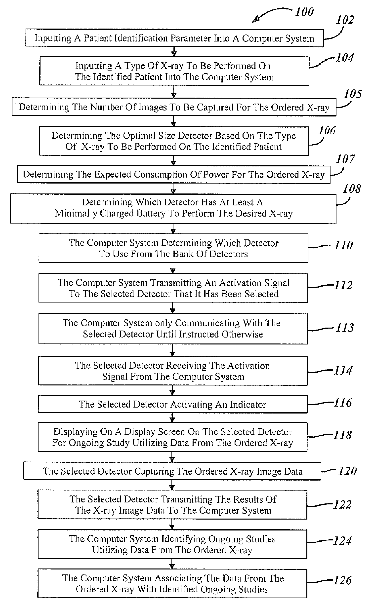
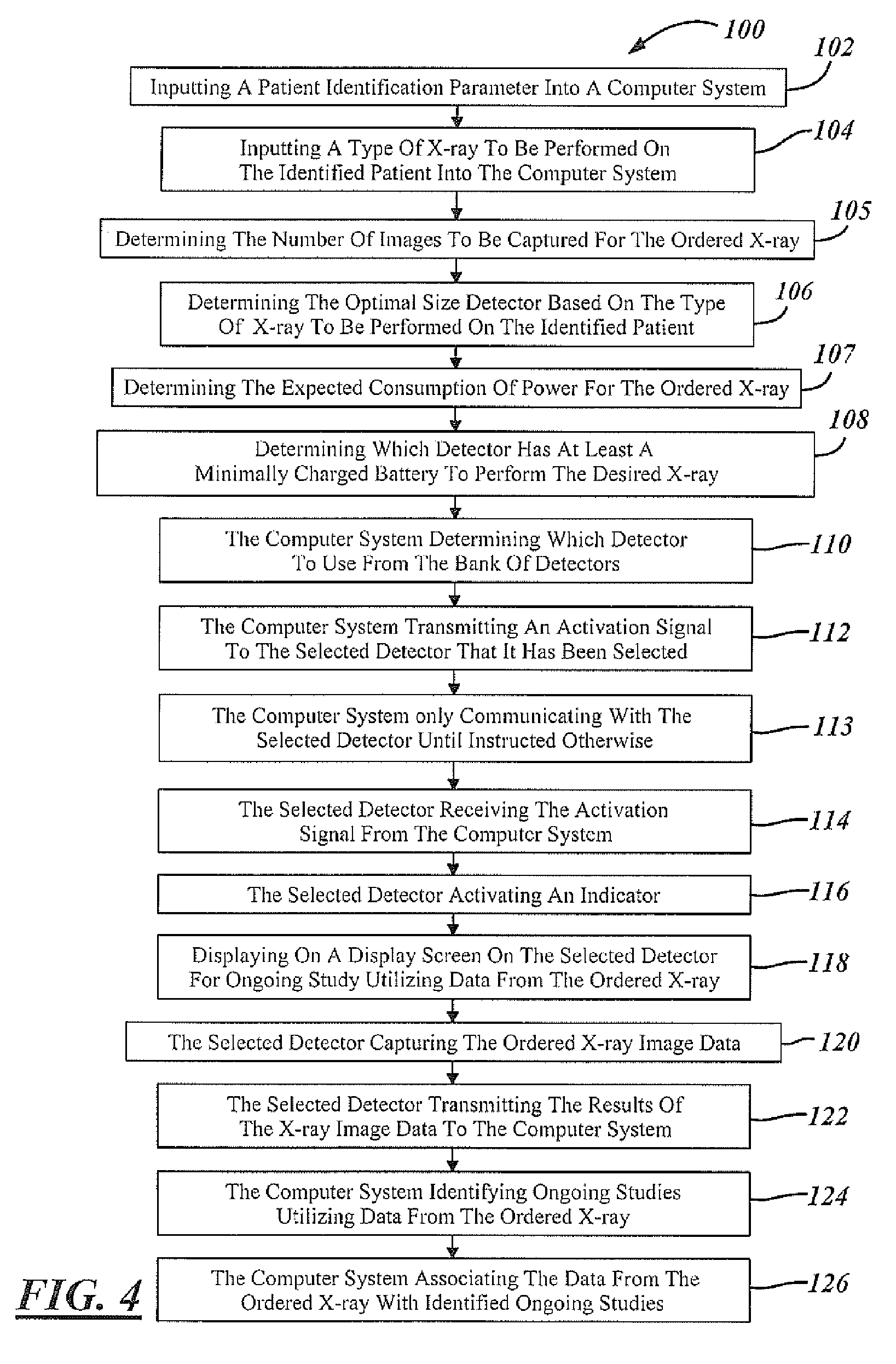
[0013]In the following figures the same reference numerals will be used to refer to the same components and methods. In the following description, various operating parameters and components are described for one constructed embodiment. These specific parameters and components are included as examples and are not meant to be limiting.

[0014]Also, in the following description various X-ray components, assemblies, and methods are described as an illustrative example. The X-ray components, assemblies, and methods may be modified depending upon the application.

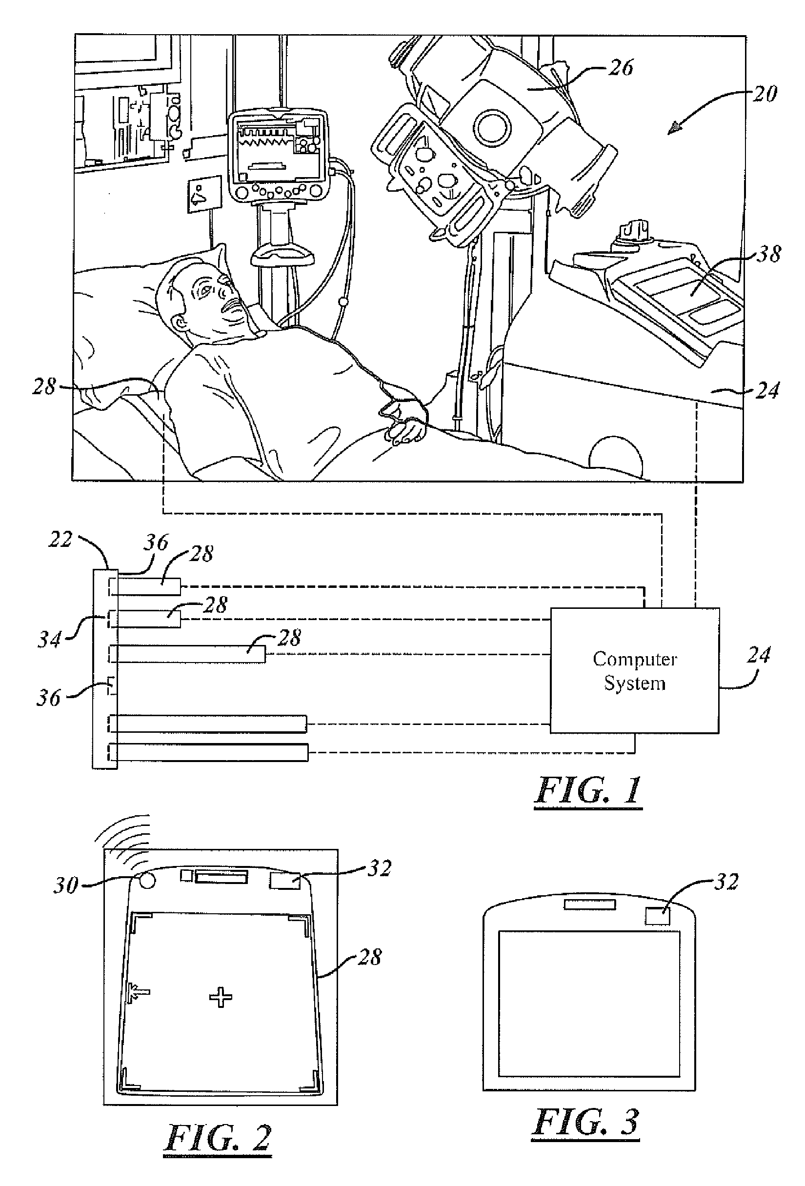
[0015]Referring now to FIG. 1, a perspective view of a X-ray system 20 utilizing a bank of wireless detectors 22 in accordance with an embodiment of the present invention is shown. The X-ray system 20 includes a computer system 24, an X-ray source 26, and a bank of various sized wireless detectors 22. Each wireless detector 28 is capable of transmitting and receiving data to and from the computer system 24 without being hard wired ...


PUM


Abstract

Methods of using an X-ray system having a central computer system, an X-ray source and a bank of wireless detectors. The methods include an automated X-ray system that requires the input of a type of X-ray to be performed on a patient, and the systems determine and identify which detector from the detector bank is appropriate for the ordered test.

Description

TECHNICAL FIELD[0001]The present invention relates generally to X-ray systems and more particularly to an X-ray system including wireless detectors of various sizes.BACKGROUND OF THE INVENTION[0002]X-ray systems are commonly used in the medical field to assist medical professionals in diagnosing ailments in patients. It is known that the hardware required for taking an X-ray includes an X-ray source and a detector. Although the need for these two fundamental components remains constant, throughout the years the components have evolved.[0003]Originally it was known to use one standard size detector for any given X-ray system and the detector utilized film to capture the image. One disadvantage of this system resulted in the patient potentially being exposed to more radiation than necessary during any given X-ray since the size of the detector could not be changed. Yet another disadvantage of this type of system is that the film needed to be processed to be useful which resulted in a ...

Claims


Application Information

Patent Timeline
Patent Type & Authority Patents(United States)
IPC IPC(8): H05G1/58
CPCA61B6/00A61B6/563A61B6/4233A61B5/117A61B6/508A61B6/4494
Inventor ABU TABANJEH, EMAD
Owner GENERAL ELECTRIC CO
Why Eureka
Try Eureka