Compensating for load pull in electromagentic signal propagation using adaptive impedance matching

a technology of adaptive impedance matching and load pull, which is applied in the field of compensating for load pull in the propagation of electromagnetic waves and signals by adaptive impedance matching system, can solve problems such as the shift of the input impedance of the amplification system

Active Publication Date: 2008-03-11
NETGEAR INC
View PDF104 Cites 20 Cited by
  • Summary
  • Abstract
  • Description
  • Claims
  • Application Information

AI Technical Summary

Problems solved by technology

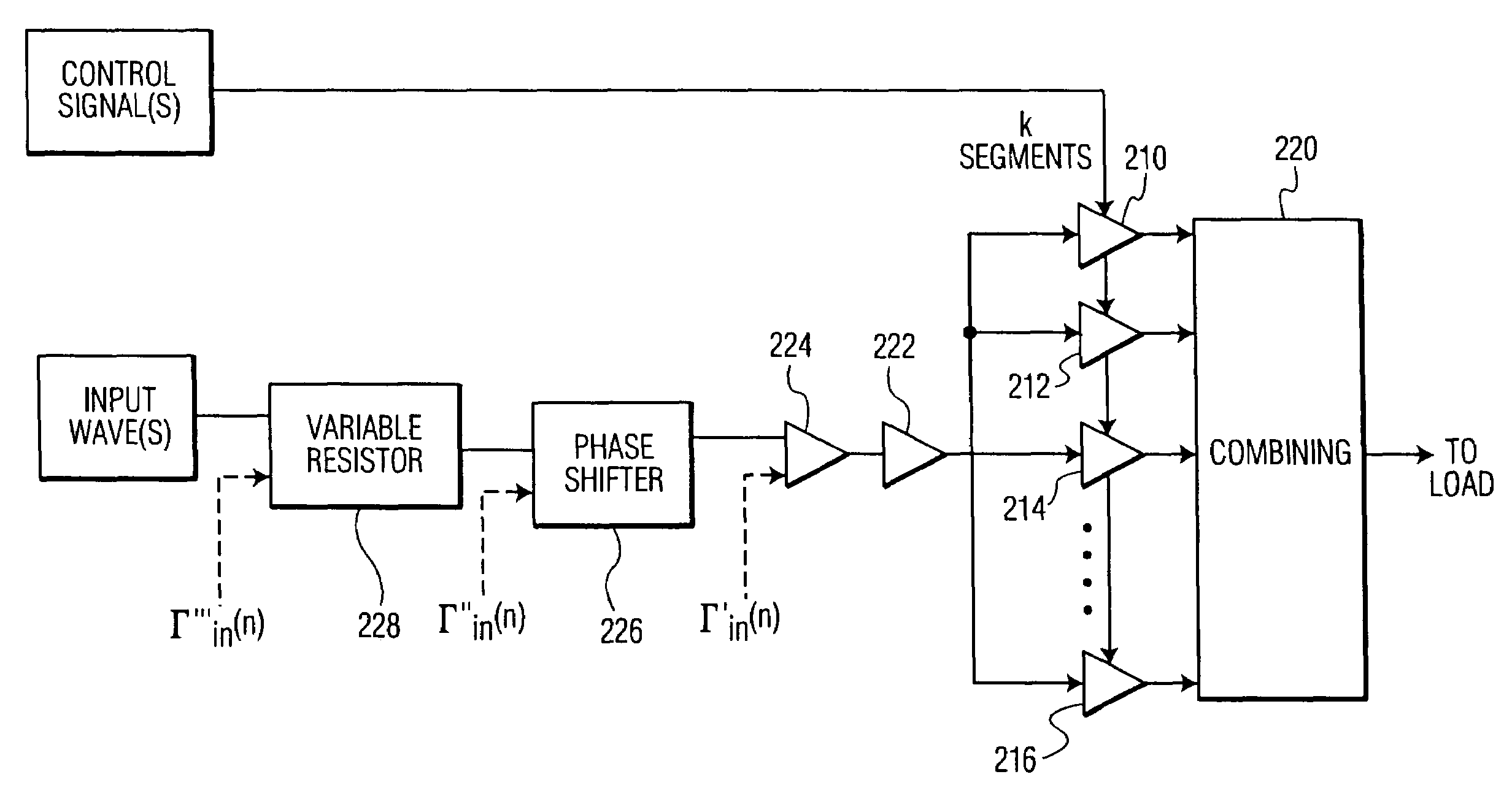
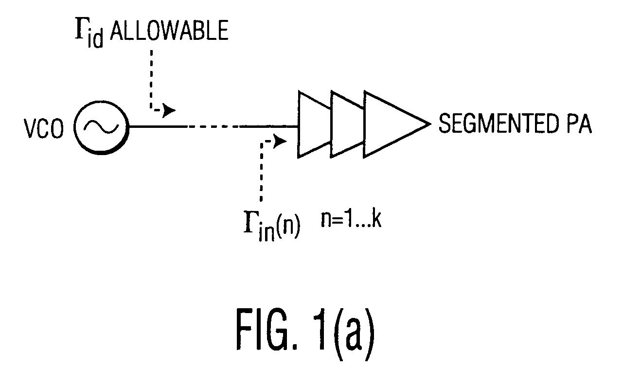
However, switching the multiple stages of the segmented amplifier in this manner may cause the input impedance of the amplification system to shift.

Method used


Image

  • Compensating for load pull in electromagentic signal propagation using adaptive impedance matching
  • Compensating for load pull in electromagentic signal propagation using adaptive impedance matching
  • Compensating for load pull in electromagentic signal propagation using adaptive impedance matching

Examples


Embodiment Construction

[0018]Embodiments of the invention include apparatus, methods and articles of manufacture for transmitting and receiving electromagnetic waves and signals. Embodiments of the invention may be entirely comprised of hardware, software and / or may be a combination of software and hardware. Accordingly, individual blocks and combinations of blocks in the drawings support combinations of mechanisms for performing the specified functions and / or combinations of steps for performing the specified functions. Each of the blocks of the drawings, and combinations of blocks of the drawings, may be embodied in many different ways, as is well known to those of skill in the art.

[0019]The word “signal” is used herein to describe an electromagnetic wave that has been modulated in some fashion, usually by the impression of intelligence upon the wave, for example imposing data upon a carrier wave. It should also be noted that the use of “signal” and “wave” in the singular includes the plural (or multipl...


PUM


Abstract

The invention relates to for processing an electromagnetic input signal, wherein the signal is passed through an input to be modified across a plurality of modifying segments using a characteristic of the signal, and wherein the plurality of segments have a plurality of states controlled by a control signal, by determining a reference impedance for the input for one or more states of the plurality of segments; and adaptively adjusting impedance of the input toward the reference impedance. This may be accomplished for example, by using a matching circuit comprising one or more selected from the group consisting of a digital signal processor, a microprocessor, a logic circuit, an integrated circuit, a phase shifter, a resistor, a variable inductor, and a variable capacitor. The matching circuit determines shifts in impedance of the input after a change in state of the segments; and adaptively adjusts the impedance based upon the shift.

Description

FIELD OF THE INVENTION[0001]The invention relates to compensating for load pull in the propagation of electromagnetic waves and signals. More particularly, the invention relates to a system for compensating for errors in electromagnetic signal propagation by adaptive impedance matching.BACKGROUND OF THE INVENTION[0002]Electromagnetic waves may be transferred from place to place through a conductor. In wired transmission, the conductor is usually a wire or other solid substance. In wireless transmission, the conductor is usually an ambient substance, such as air, water, etc. In wireless connections a transmitter is usually used to transfer a wave and a receiver to receive a wave. A transceiver combines the functions of both transmitter and receiver in one system. A transmitter typically converts electrical energy into a signal, which is then broadcast via an antenna to a receiver's antenna. Repeaters, middle stations, etc. may be used as intermediates in the transmission to sustain t...

Claims


Application Information

Patent Timeline
Patent Type & Authority Patents(United States)
IPC IPC(8): H04B1/04H03F1/56H03F3/21H03F3/60
CPCH03F1/56H03F3/211H03F3/602H03F2200/331
Inventor BENGTSON, DAVIDDOUGLAS, DALE SCOTT
Owner NETGEAR INC
Why Eureka
Try Eureka