Intralumenal material removal using a cutting device for differential cutting

a cutting device and intralumenal material technology, applied in the field of systems and methods for removing materials, can solve the problems of inability to remove hard materials, manifestly critical safety and reliability of the system, and inability to deform hard materials, etc., to achieve the effect of reducing the viscosity of materials, facilitating removal through relatively small diameter lumens, and reducing the complexity and rigidity of materials

Inactive Publication Date: 2008-03-18
BOSTON SCI LTD
View PDF28 Cites 346 Cited by
  • Summary
  • Abstract
  • Description
  • Claims
  • Application Information

AI Technical Summary

Benefits of technology

[0016]According to one embodiment of the present invention, the removal system comprises a cutter assembly having blades that are specially designed and arranged to cut or scrape matter while not damaging other beneficial material, or at least doing minimal damage to such beneficial material. The blades are provided at acute angles of attack, generally less than 90 degrees.
[0017]The cutter assembly may be either fixed or adjustable in diameter. In one particular embodiment, an expandable cutter is adjustable between a smaller diameter condition, in which it may be guided to and withdrawn from the desired material removal site, and a larger diameter condition, in which it may be operated during a material removal operation. The expandable cutter may thus be introduced to and withdrawn from the material removal site in a retracted, smaller diameter condition that facilitates translation and navigation of the device through various lumens, such as blood vessels. The expandable cutter may be selectively expanded at the material removal site to facilitate cutting, removal and aspiration of the material desired to be removed.
[0020]In one embodiment, the cutter assembly drive shaft operates bidirectionally and the adjustable diameter cutter is expanded or retracted selectively and controllably upon rotation in opposite directions. Upon rotation of the drive shaft and dual cutter assembly in a first direction, the fixed diameter cutter is used as the primary cutter and the expandable cutter remains in a smaller diameter condition, while upon rotation of the dual cutter assembly in a second direction, opposite the first, the expandable cutter is in a larger diameter condition and serves as the primary cutter. The present invention uses hydrodynamic, centrifugal and / or frictional forces to expand and contract the dual cutter assembly, thereby obviating the need for additional actuation systems, which add considerable complexity and rigidity to such systems.
[0021]Liquid infusion may be provided in proximity to the cutter assembly in addition to or alternatively to aspiration. Infusion of liquids may be used to provide additional liquids for materials removal or to deliver lubricating fluids, treatment agents, contrast agents, and the like. Infusion of fluids in proximity to the area of a material removal operation may be desirable because it tends to reduce the viscosity of the materials being removed, thus facilitating removal through relatively small diameter lumens. Infusion of liquids also desirably tends to reduce the volume of blood removed during the operation. According to one embodiment, a sealed lumen formed between the cutter assembly drive shaft and a catheter may alternatively and selectively be used as aspirate removal system and an infusion system. The sealed lumen may thus be selectively connectable to a vacuum source and aspirate collection system for aspiration, and an infusion source for infusion of liquids. Ports in or in proximity to the cutter assembly may be thus be employed, selectively, as aspiration and infusion ports.

Problems solved by technology

In some cases, undesirable matter may exist or become lodged within the cavity and must be removed by the practitioner.
Some procedures for removing undesirable matter involve the challenging operation of maneuvering a cutting device within small confines of interior body cavities.
Despite the varied approaches to the systems and methods exemplified by the U.S. patents cited above, many challenges remain in providing systems and methods for removing material from a lumen, such as a blood vessel, safely and reliably and without causing complications.
The safety and reliability of the system is manifestly critical.
Harder material is not able to deform when contacted by the differential cutting blade, and shear stresses are consequently exerted on the more rigid material.
This diamond grit surface forms random angles of attack and creates random cutting characteristics at various points of contact with the target undesired matter.
In using diamond grit cutting devices, when applying increased depth of force of the device into the target matter to be removed, there is a greater risk of cutting into the supporting beneficial material in proximity to the target undesired matter.
Thus, these prior devices require extreme caution in use in order to avoid cutting beneficial material.
One of the particular challenges of removing matter from the interior of lumens is that the drive and cutter assemblies must be small enough and flexible enough to travel over a guidewire to a desired material removal site, such as the site of an obstruction or occlusion.
The size and consistency of the material comprising an obstruction are frequently not well characterized prior to introduction of the material removal device.
Thus, although devices and cutters having different sizes and properties may be provided, and may even be interchangeable on a material removal system, it is difficult to ascertain which combination of features is desired in any particular operation prior to insertion of the device.
The use of multiple cutter assemblies having different properties during a materials removal operation is inconvenient at best, since it requires removal of each independent device and interchange of the cutter assemblies, followed by reinsertion of the new cutter assembly, or of a new device entirely.
Interchange and reinsertion of cutter assemblies is time consuming and generally deleterious to the health and condition of the patient undergoing the procedure.

Method used


Image

  • Intralumenal material removal using a cutting device for differential cutting
  • Intralumenal material removal using a cutting device for differential cutting
  • Intralumenal material removal using a cutting device for differential cutting

Examples


Embodiment Construction

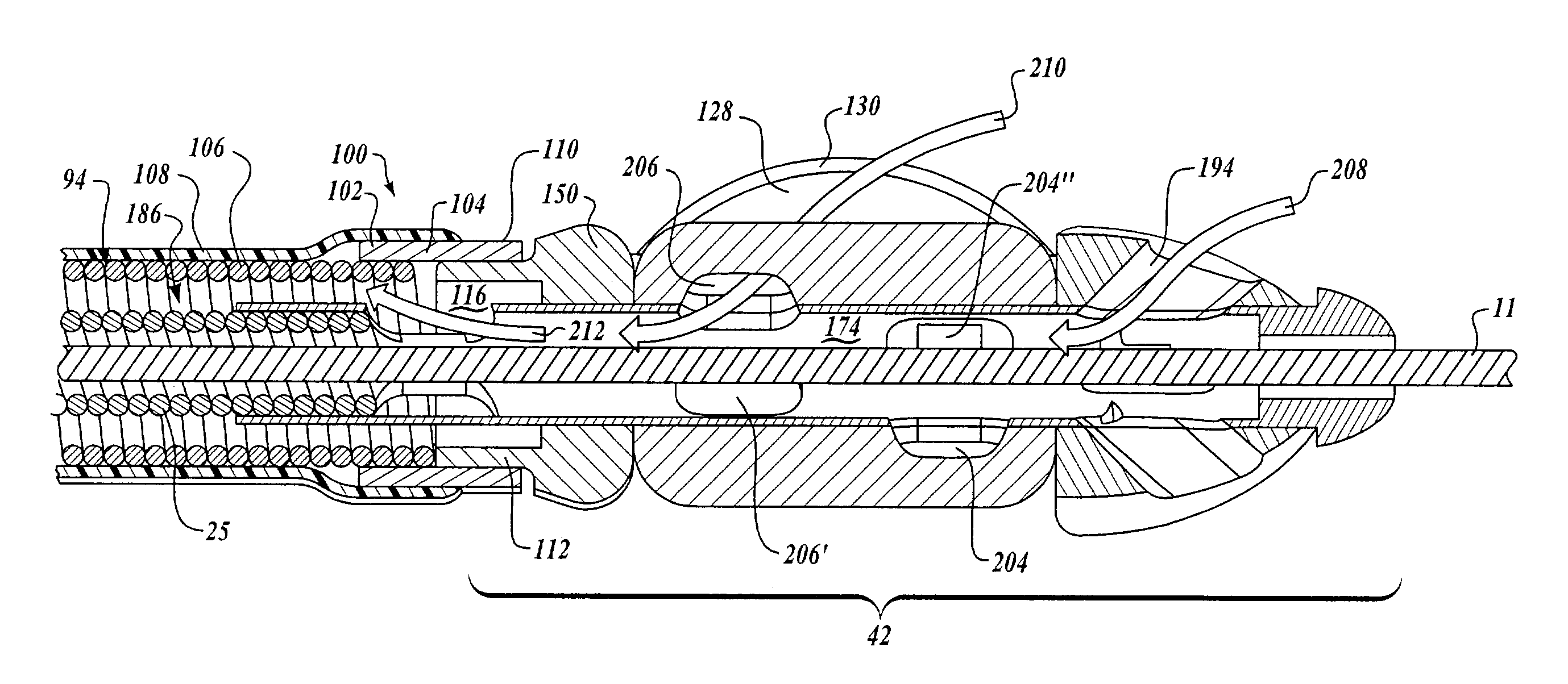
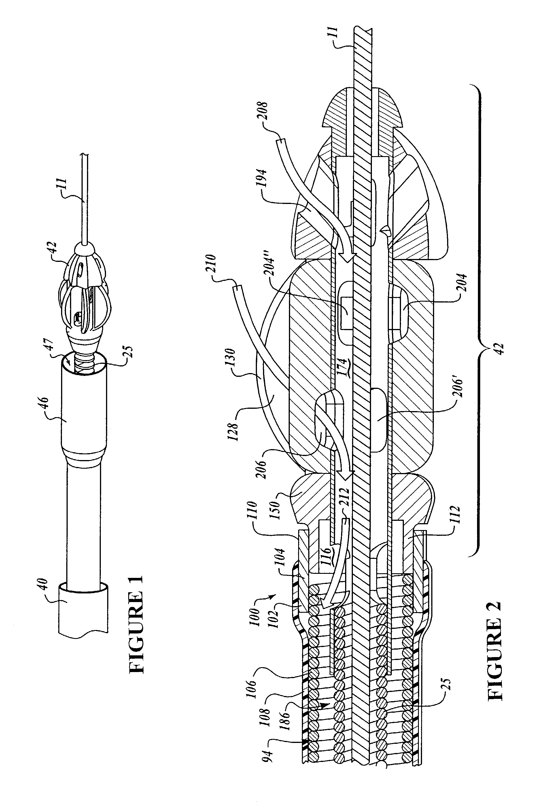
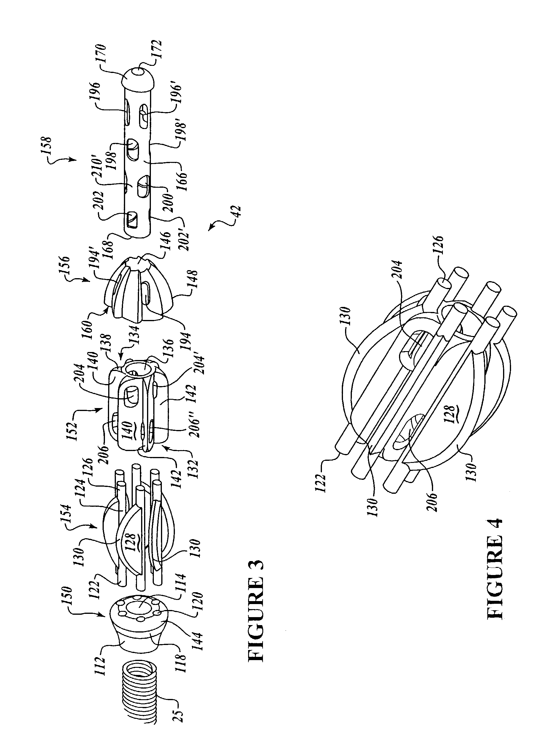
[0044]As used herein in the description of various components, “proximal” or “antegrade” refers to a direction toward the system controls and the operator along the path of a drive system, and “distal” or “retrograde” refers to the direction away from the system controls and the operator and toward or beyond a terminal end of the cutter assembly. In general, the material removal system of the present invention comprises a cutter assembly positioned at the distal end of the material removal system.

[0045]Exemplary material removal systems, components and subassemblies suitable for use in connection with methods and systems of the present invention are disclosed and described in the U.S. patents incorporated herein by reference, and in PCT Patent Publication WO 01 / 76680, entitled “Intralumenal Material Removal Systems and Methods”, which is incorporated herein by reference in its entirety. In particular embodiments, cutter blades of the cutter assembly operate according to differential...


PUM


Abstract

Intralumenal material removal systems are provided using an advanceable and rotatable cutter assembly designed for differential cutting. The intralumenal material removal system includes a cutter assembly positionable in the body cavity of a mammalian subject. One embodiment of the cutter assembly includes a cutter with blades that are designed and arranged to form an acute blade angle of attack with the matter-to-be-removed. The cutter assembly is axially advanceable by translating the drive shaft and rotatable by rotating the drive shaft. The occlusive material is scraped by the cutter assembly and may be aspirated to remove the material from the body cavity. The cutter assembly may provide aspiration ports positioned between facing surfaces of the blades.

Description

CROSS-REFERENCE TO RELATED APPLICATIONS[0001]This application is a continuation-in-part of U.S. patent application Ser. No. 09 / 724,914 filed on Nov. 28, 2000 and issued as U.S. Pat. No. 6,565,588 on May 20, 2003, which claims priority under 35 U.S.C. §119(e) to U.S. Provisional Patent Application No. 60 / 194,805, filed Apr. 5, 2000. The disclosures of the aforementioned applications are herein incorporated by reference in their entirety. This application also claims priority under 35 U.S.C. §119(e) to U.S. Provisional Patent Application No. 60 / 453,846 filed Mar. 10, 2003.FIELD OF THE INVENTION[0002]The present invention relates to systems and methods for removing material, such as obstructions and partial obstructions, from a body cavity of a mammalian subject, such as a blood vessel. More particularly, the present invention relates to systems and methods for removing material from a cavity of a mammalian subject using a rotatable cutter assembly having blades designed for differenti...

Claims


Application Information

Patent Timeline
Patent Type & Authority Patents(United States)
IPC IPC(8): A61B17/3207A61B17/22A61B1/01A61B8/12A61B17/00A61B17/28A61B17/32A61B17/34A61M1/00A61M25/18A61M39/06
CPCA61B5/061A61M25/0147A61B5/418A61B8/4209A61B17/320725A61B17/320758A61M39/06A61B5/415A61B8/12A61B17/32002A61B17/3462A61B2017/00017A61B2017/00199A61B2017/00973A61B2017/22049A61B2017/2927A61B2017/320032A61B2217/005A61M39/0606A61M2039/062
Inventor WULFMAN, EDWARD I.TORRANCE, CASEYNISTAL, BRENTYOUMANS, SCOTT
Owner BOSTON SCI LTD
Why Eureka
Try Eureka