
Method for color cast removal in scanned images

a color cast and scanned image technology, applied in the field of electronic imaging, can solve the problems of image degradation, color cast is generally considered an overall color imbalance in an image, and the predominance of color ruins the whole image, so as to achieve the effect of eliminating possible quantization errors

Inactive Publication Date: 2008-03-18
XEROX CORP
View PDF16 Cites 2 Cited by
  • Summary
  • Abstract
  • Description
  • Claims
  • Application Information

AI Technical Summary

Benefits of technology

[0010]A method for correcting color casts in L*a*b* space, according to the invention, allows the user to displace the middle of the neutral axis by a given a* and b* value, while going to the proper white and black point at the end points. The method of the invention also keeps the displaced colors from being pushed out of gamut by decreasing the change in a* and b* for large a* and b*. The method of the invention overcomes the problems of previous methods which work in CMY or RGB space and require two color mapping steps for use on an L*a*b* image, potentially causing image degradation through quantization and round-off errors. The method of the invention eliminates the need for such extra mapping, saving time and preserving image quality.
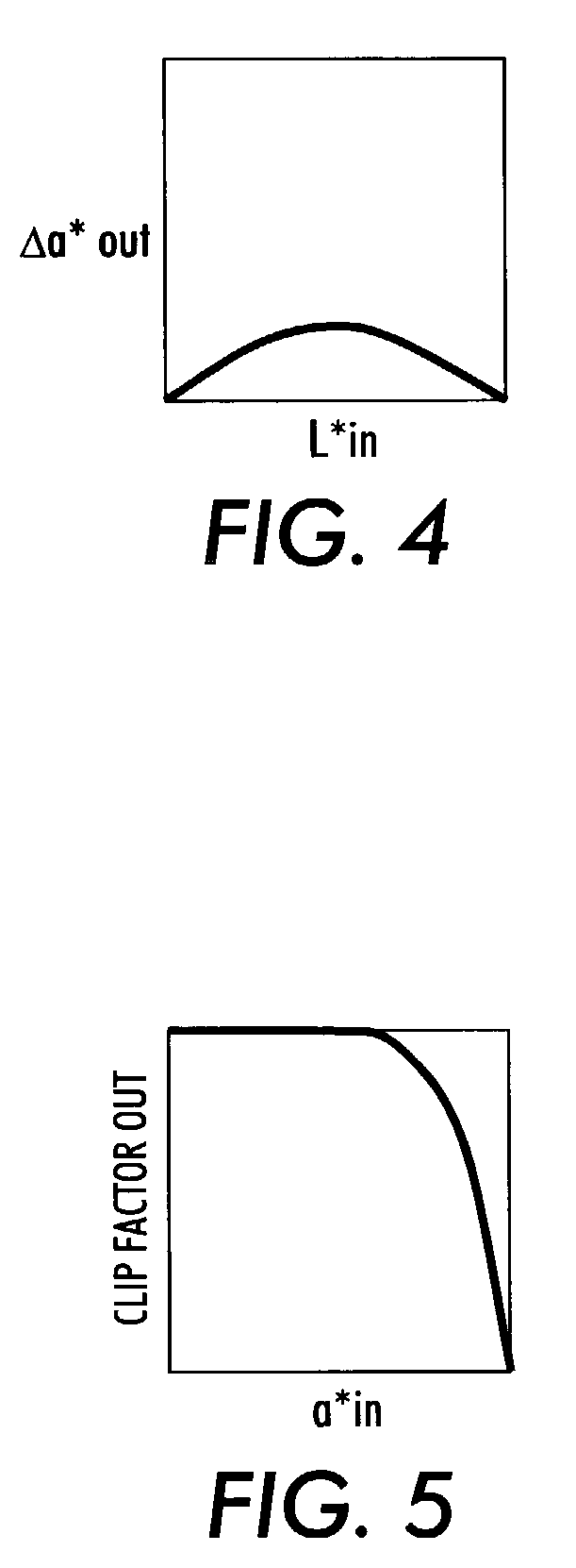
[0015]The method of the invention allows color cast removal to be performed in the L*a*b* color space, thus eliminating possible quantization errors from converting to and from RGB or CMY color spaces in processing scanned images. Instead of passing the a* and b* separations through a full-scale to full-scale TRC, a color cast correction value is is calculated for each pixel (from the color cast correction curve) and added to the a*b* separations. The color cast correction value is based on the desired a*b* shift in the midtones, but is modulated as a function of the L* luminance so that the white point and black point are not effected. The color cast correction value may also be further modified as a function of a* and b* so that the resulting sum will tend to remain within the gamut when a* or b* is near the edge of the space.

Problems solved by technology

Color cast is generally considered an overall color imbalance in an image, as if viewed through a color filter.
The predominance of the color ruins the whole image.
When the image path is processing in a different color space (such as CIE L*a*b*), changing into and back out of RGB or CMY can be time consuming and may result in image degradation due to quantization errors and round-off errors.
When the image path is processing in L*a*b* space, simply adding an offset in a* and b* can result in a change in an established white point as well as illegal values outside the color gamut.
Behlok does not address the generation of the specific TRC's to adjust the particular image characteristics.
U.S. Pat. No. 4,972,257 to Birnbaum, et al. for “Operator Adjustable Color Image Processing” discusses color correction in L*a*b* space, but the described techniques are not suitable for color cast correction.
Automatic color cast determination does not afford an operator the ability to adjust for color cast to make a more humanly aesthetic color appearance.

Method used


Image

  • Method for color cast removal in scanned images
  • Method for color cast removal in scanned images
  • Method for color cast removal in scanned images

Examples


Embodiment Construction

[0019]Previous methods for performing color cast correction (or hue shift) used RGB space or CMY space, where three TRC's were generated to make small adjustments in each of the separations as needed. Exemplary TRC's for cyan, magenta and yellow are shown in FIGS. 1-3, respectively. Many image processing systems use L*a*b* space in the image path, it is desirable to perform any color cast correction in the same space in order to avoid multiple quantization steps in conversion between spaces.

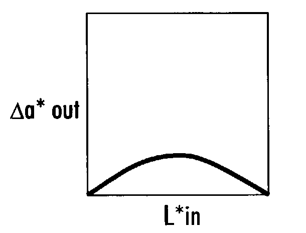
[0020]Instead of a full-scale to full-scale TRC, the method of the invention uses a color correction curve based on L* for each of a* and b*, and then multiplies the result by a clipping function to ensure that the new values do not exceed full scale. Referring to FIG. 4, a color cast correction curve according to the invention is shown. This curve has L* as the X-axis and Δa* as the Y-axis. When L* has a zero value (it is black), Δa* is zero. Similarly, when L* has its maximum value (it is white...


PUM


Abstract

A method for color cast removal in a scanned image in L*a*b* space includes generating a first color cast correction curve for mapping L* to a first color correction, Δa*, (or Δb*) wherein the first correction curve provides a desired a* shift in midtone regions and is modulated as a function of L* such that black and white points are unaffected; for each pixel n in the scanned image, passing L*n through the first color cast correction curve for obtaining a value of Δa*n; and adding the value of Δa*n to the scanned image's original a*n component. To ensure that the color corrected a* remains within gamut, a second correction curve for applying a clipping factor to the mapped Δa* may be generated with the a*n passing through the second correction curve for obtaining a clipping factor Cn; and modifying the a*n value by Cn(Δa*n).

Description

FIELD OF THE INVENTION[0001]This invention relates generally to electronic imaging, and more particularly, to a method of removing color cast in scanned images.BACKGROUND OF THE INVENTION[0002]Color cast is generally considered an overall color imbalance in an image, as if viewed through a color filter. Color cast appears when one dominant color appears as a trace in all other colors in an image. The predominance of the color ruins the whole image. Many images will have a single-color cast, where for example, the entire image has a blue tint, or a red tint, or a yellow tint. There are also color casts with hues between primary colors, such as yellow / green as opposed to a pure yellow cast. There are many techniques for removing color cast, such as background removal and hue shift. Background removal linearly stretches or normalizes each separation such that the lightest pixels are mapped into white. Hue shift adds or subtracts a color at each pixel.[0003]Previous methods for performi...

Claims


Application Information

Patent Timeline
Patent Type & Authority Patents(United States)
IPC IPC(8): G06F15/00H04N1/60
CPCH04N1/608
Inventor RUMPH, DAVID E.HAINS, CHARLES M.
Owner XEROX CORP
Learn More