Combined total-internal-reflectance and tissue imaging systems and methods

a total-internal reflection and tissue imaging technology, applied in the field of biometrics, can solve the problems of poor image contrast, particularly susceptible to image quality problems, and the tir at this location is frustrated

Active Publication Date: 2008-03-25
HID GLOBAL CORP
View PDF240 Cites 99 Cited by
  • Summary
  • Abstract
  • Description
  • Claims
  • Application Information

AI Technical Summary

Problems solved by technology

Alternatively, if skin of the proper index of refraction is in optical contact with the platen, then the TIR at this location is “frustrated,” allowing light to traverse the platen-skin interface or, in some arrangements, allowing the light to traverse the interface at an angle that is unavailable when TIR phenomena are present at the location.
Although TIR fingerprint sensors are the most common form of optical fingerprint readers, they are particularly susceptible to image quality problems due to non-ideal conditions.
If the skin is overly dry, the index match with the platen will be compromised, resulting in poor image contrast.
Similarly, if the finger is very wet, the valleys may fill with water, causing an optical coupling to occur all across the fingerprint region and greatly reducing image contrast.
These effects decrease image quality and thereby decrease the overall performance of the fingerprint sensor.
As a soft material, the membrane is subject to damage, wear, and contamination, limiting the use of the sensor without maintenance and limiting the environments in which the sensor can be used.
Biometric sensors, particularly fingerprint biometric sensors, are generally prone to being defeated by various forms of spoof samples.
Thus, even if a fingerprint reader can be considered to reliably determine the presence or absence of a matching fingerprint pattern, it is also critical to the overall system security to ensure that the matching pattern is being acquired from a genuine, living finger, which may be difficult to ascertain with many common sensors.

Method used


Image

  • Combined total-internal-reflectance and tissue imaging systems and methods
  • Combined total-internal-reflectance and tissue imaging systems and methods
  • Combined total-internal-reflectance and tissue imaging systems and methods

Examples


Embodiment Construction

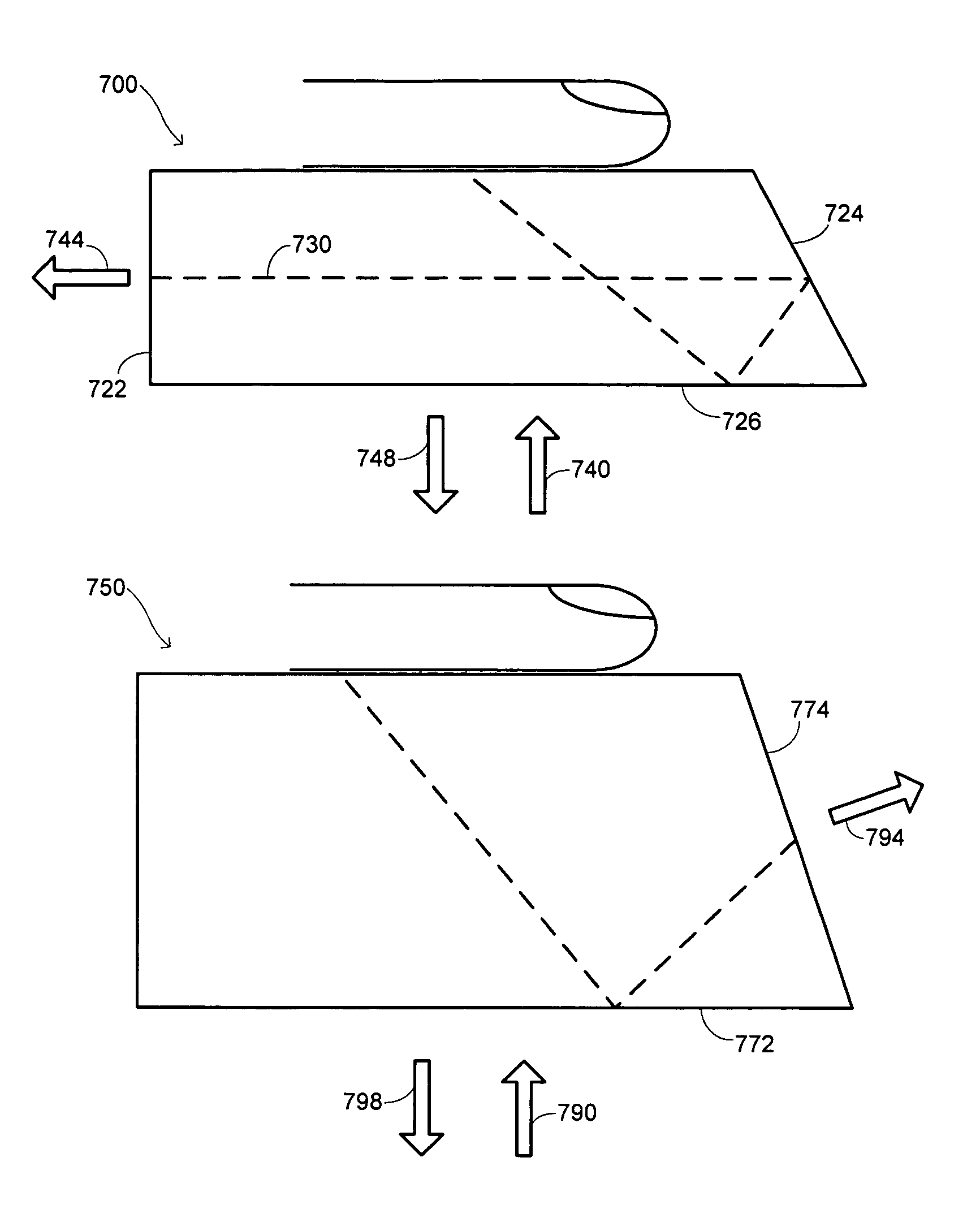
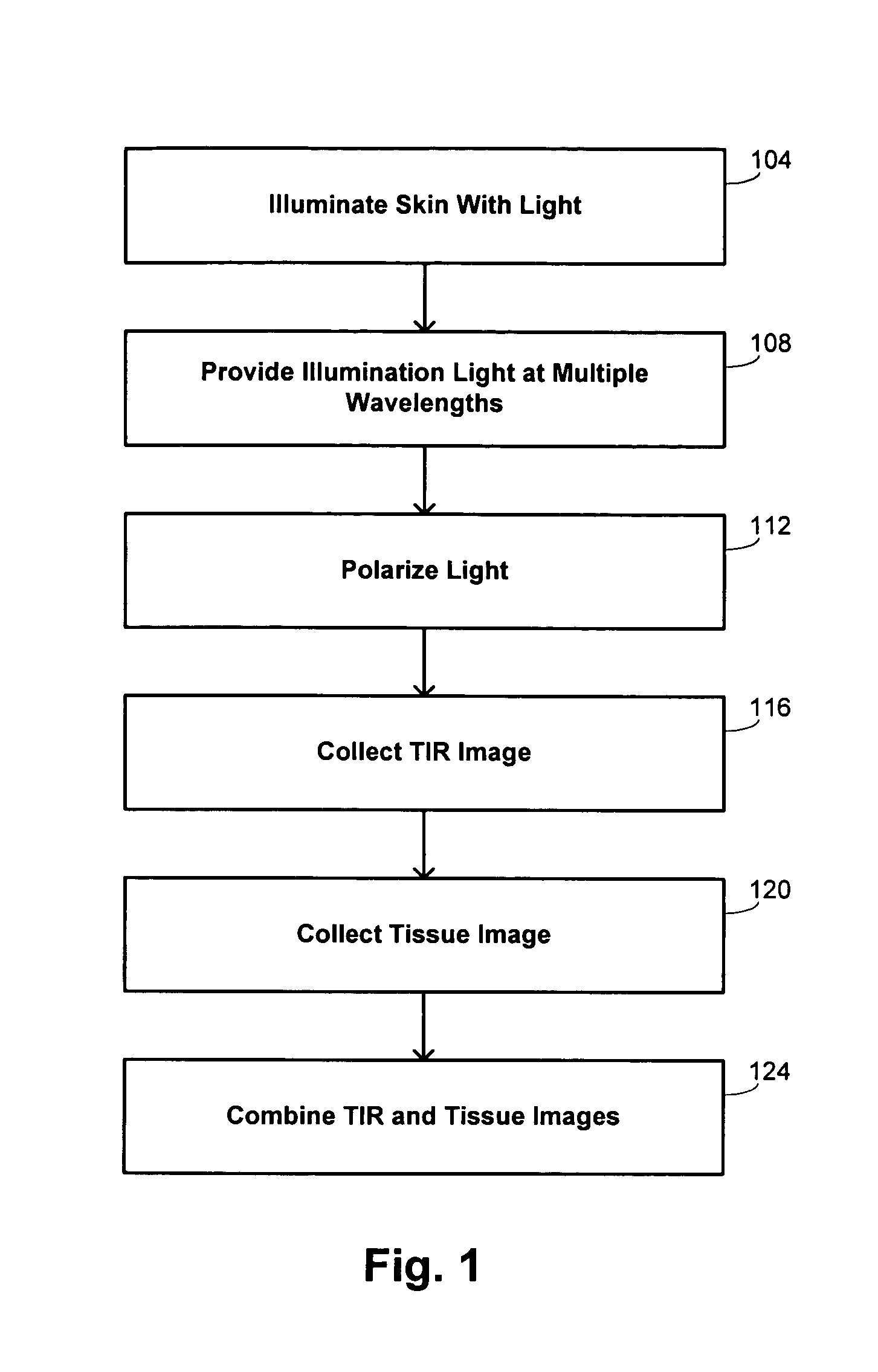
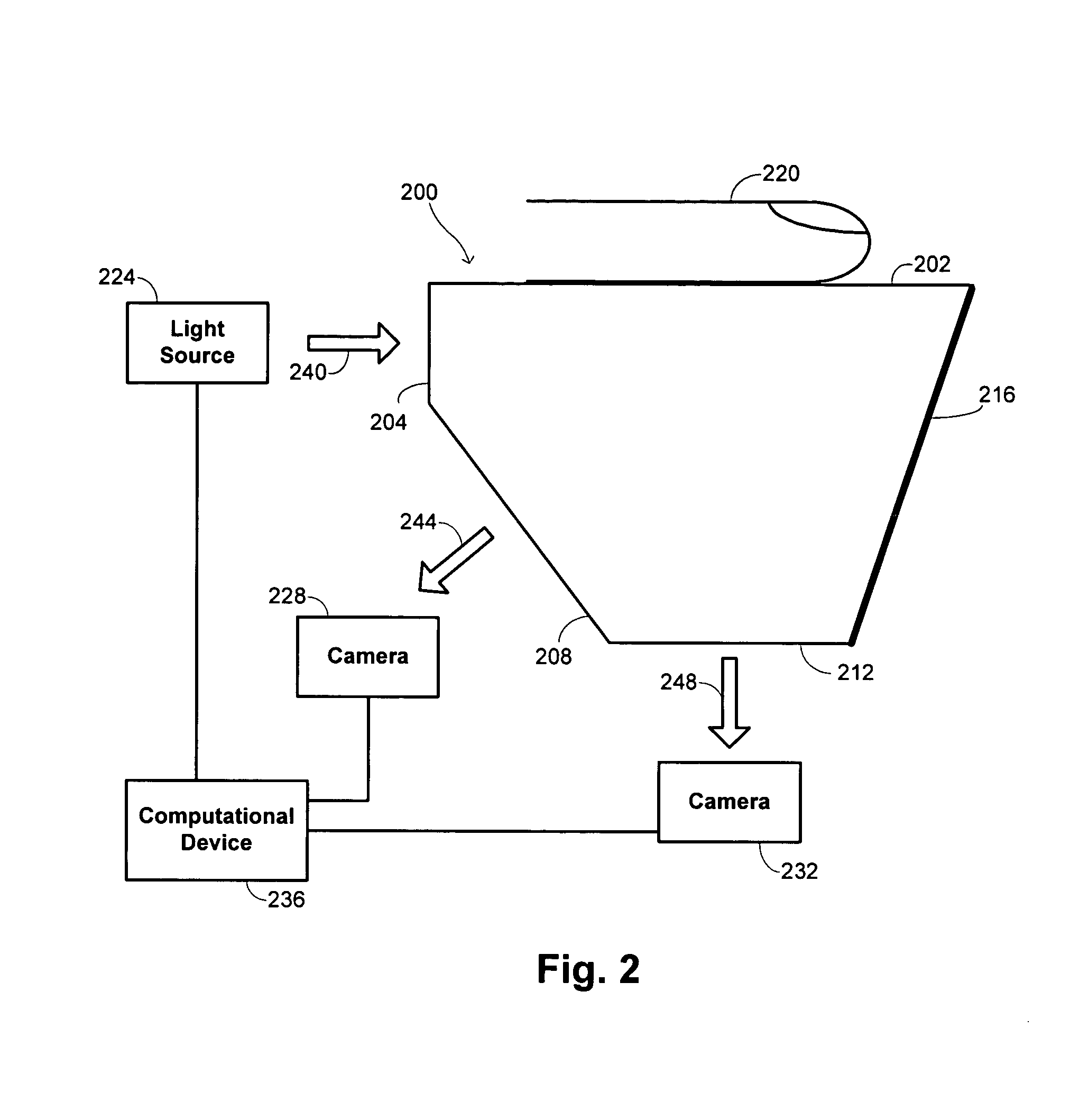
[0033]Embodiments of the invention provide systems that may combine TIR and tissue imaging systems. The TIR component examines the optical interface between skin and a platen, thereby providing a map outlining regions of contact and regions without contact. The tissue-imaging component results from measurements of light that scatter within tissue below the surface of the skin. In some embodiments, the wavelength ranges comprise the ultraviolet, visible, very-near-infrared, or near-infrared ranges, or combinations of these ranges. Embodiments of the invention collect images taken under a plurality of optical conditions, such as with different wavelengths and / or polarization conditions. Such embodiments are referred to herein as providing “multispectral” optical conditions, as may be provided by using polychromatic illumination sources, including polarizing elements in optical trains used to direct light, and the like. Collection of multispectral data is advantageously robust to non-i...


PUM


Abstract

Methods and systems are provided for combining total-internal-reflectance and tissue imaging to perform biometric functions. The system may include an illumination source, a platen, a light detector, an optical train, and a computational unit. The platen is disposed to make contact with a skin site of an individual. The optical train is disposed to provide optical paths between the illumination source and the platen, and between the platen and the light detector. The combination of the illumination source and optical train provides illumination to the platen under multispectral conditions. The computational unit is interfaced with the light detector and has instructions to generate a total-internal-reflectance image of the skin site from a first portion of light received from the skin site, and to generate a tissue image of the skin site from a second portion of light received from the skin site.

Description

CROSS-REFERENCES TO RELATED APPLICATIONS[0001]This application is a continuation-in-part of U.S. patent application Ser. No. 10 / 818,698, entitled “MULTISPECTRAL BIOMETRIC SENSOR,” filed Apr. 5, 2004 by Robert K. Rowe et al., which is a nonprovisional of U.S. Prov. Pat. Appl. No. 60 / 460,247, entitled “NONINVASIVE ALCOHOL MONITOR,” filed Apr. 4, 2003; U.S. Prov. Pat. Appl. No. 60 / 483,281, entitled “HYPERSPECTRAL FINGERPRINT READER,” filed Jun. 27, 2003 by Robert K. Rowe et al.; U.S. Prov. Pat. Appl. No. 60 / 504,594, entitled “HYPERSPECTRAL FINGERPRINTING,” filed Sep. 18, 2003; and U.S. Prov. Pat. Appl. No. 60 / 552,662, entitled “OPTICAL SKIN SENSOR FOR BIOMETRICS,” filed Mar. 10, 2004.[0002]This application is also related to commonly assigned U.S. patent application Ser. No. 09 / 874,740, entitled “APPARATUS AND METHOD OF BIOMETRIC DETERMINATION USING SPECIALIZED OPTICAL SPECTROSCOPY SYSTEM,” filed Jun. 5, 2001.[0003]The entire disclosure of each application identified above is incorpora...

Claims


Application Information

Patent Timeline
Patent Type & Authority Patents(United States)
IPC IPC(8): G06K5/00A61B5/00A61B5/117B60R25/00G06K9/00
CPCA61B5/0059A61B5/117A61B5/14546A61B5/441B60R25/25B60R25/252B60R25/255B60R25/257G06K9/00046G06K9/0012A61B5/145A61B5/1171G06V40/1324G06V40/1394G06T1/00G06F18/00
Inventor ROWE
Owner HID GLOBAL CORP
Why Eureka
Try Eureka