
Capacitive input device

a technology of input device and input device, which is applied in the direction of coding, pulse technique, instruments, etc., can solve the problems of reducing the size of the input device, reducing and reducing so as to improve the operability of the input device and reduce the size of the electronic apparatus

Active Publication Date: 2008-03-25
ALPS ALPINE CO LTD
View PDF6 Cites 68 Cited by
  • Summary
  • Abstract
  • Description
  • Claims
  • Application Information

AI Technical Summary

Benefits of technology

The present invention provides an input device with a double-sided-input-type capacitive sensor that can detect inputs from both sides of the sensor. This improves the operability of the input device and reduces the size of the electronic apparatus having the input device. The input device includes a clock signal generator, a delay unit, protective sheets, a logical product unit, and a controller. The protective sheets are formed of a dielectric and are disposed on both sides of the capacitive sensor. The controller controls the input through the front and rear surfaces of the capacitive sensor based on the output signal obtained from the sensor. The invention also provides an electronic apparatus with a capacitive sensor and insulating sheets that can discriminate between input operation on the first and second insulating sheets. The technical effects of the invention are improved operability and reduced size of the input device.

Problems solved by technology

However, as the electronic apparatus has become smaller in recent years, it has been required that the input device installed in the electronic apparatus becomes smaller.
As a result, since the input surface of the input device becomes smaller, there is a problem in that operability of the input device becomes deteriorated.
Specifically, an area of the input surface becomes smaller with decreasing size of the electronic apparatus and the input device while it is difficult for the sizes of the finger or pen operating the electronic apparatus to become smaller.
For this reason, there is concern that the operator may erroneously operate a minute input key formed on the input surface.
However, in an input device having a capacitive sensor according to the related art, there is a problem in that an input surface of the capacitive sensor is limited to any one of a front surface and a rear surface of the capacitive sensor.

Method used


Image

  • Capacitive input device
  • Capacitive input device
  • Capacitive input device

Examples


first embodiment

[0026]Hereinafter, a first embodiment of the invention will be described with reference to FIGS. 1 to 4.

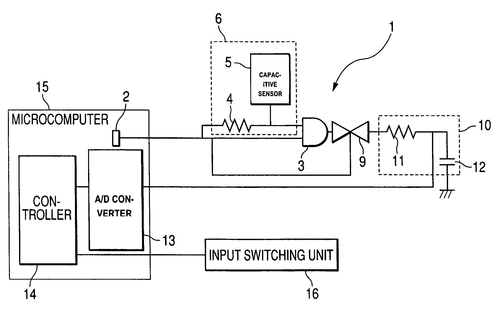
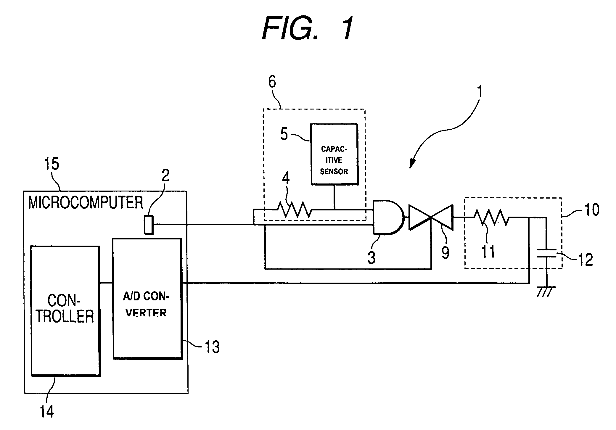
[0027]As shown in FIG. 1, an input device 1 according to the first embodiment of the invention is an electronic circuit that includes a microcomputer 15, a delay unit 6, a logic product unit 3, an analog switch 9, and a smoothing unit 10.

[0028]The microcomputer 15 has a clock signal generator 2, an A / D converter 13, and a controller 14. The clock signal generator 2 generates a clock signal CK which becomes a driving wave of the input device 1 according to the present embodiment, and is connected to one input terminal of the logic product unit 3. The A / D converter 13 converts an analog output into a digital output and is connected to the smoothing unit 10 and the controller 14. The controller 14 selects any used program from a plurality of programs built in the microcomputer 15 and controls it. Any of the plurality of programs can be selected using a digital output transmitted from...

second embodiment

[0049]Hereinafter, a second embodiment of the invention will be described with reference to FIGS. 5 and 6. As shown in FIG. 5, since the input device 1 according to the second embodiment has the approximately same structure and effect as the input device according to the first embodiment, only a portion of the input device according to the second embodiment different from the input device according the first embodiment will be described.

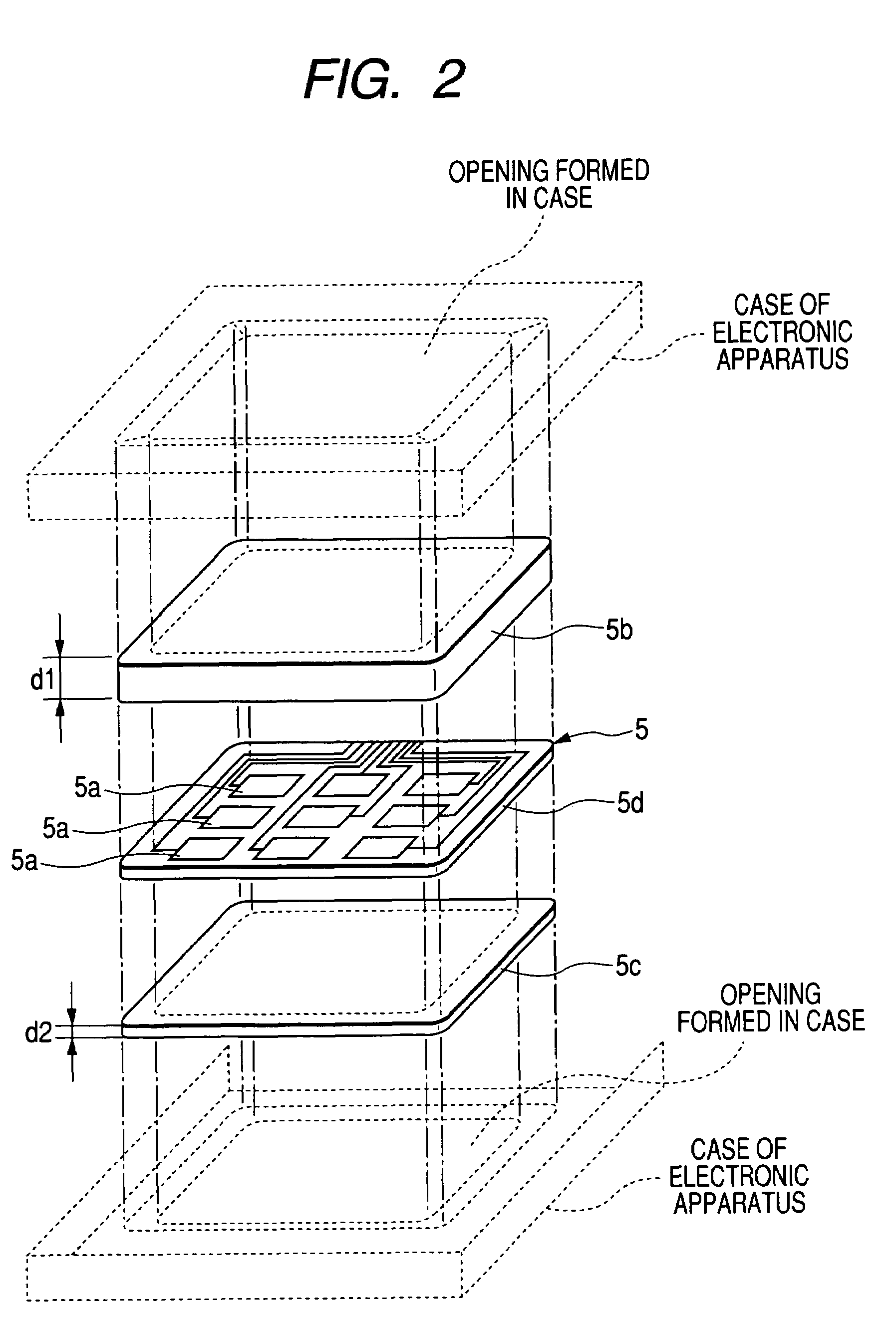
[0050]Similarly to the input device 1 according to the first embodiment, the input device 1 according to the second embodiment is an electronic circuit that includes a microcomputer 15, a delay unit 6, a logical product unit 3, an analog switch 9, and a smoothing unit 10. However, the input device 1 according to the second embodiment is different from the input device according to the first embodiment in a thickness of each of protective sheets 5b and 5c of a capacitive sensor 5 provided in the delay unit 6, and an input switching unit 16 connected t...


PUM


Abstract

A input device is provided which includes a clock signal generator that generates a clock signal; a delay unit that has a capacitive sensor where an electrode is formed on a substrate; protective sheets each of which is formed of a dielectric and which are disposed on front and rear surfaces of the capacitive sensor; a logical product unit that transmits an output signal on the basis of a clock signal obtained from the clock signal generator and a delay signal obtained from the delay unit; and a controller that makes a predetermined program executed in accordance with an output signal obtained on the basis of the logical product unit.

Description

BACKGROUND OF THE INVENTION[0001]1. Field of the Invention[0002]The present invention relates to an input device capable of performing an input through a front surface and a rear surface of a capacitive sensor so as to detect a variation of a capacitance, and, more particularly, to an input device suitable for a portable electronic apparatus which requires complicated input operation.[0003]2. Description of the Related Art[0004]Generally, an input unit, which has a capacitive sensor for detecting a variation of a capacitance, has been widely used in various electronic apparatuses. For example, it has been used as an input device for inputting information such as figures, characters or the like in electronic apparatuses such as a cellular phone, a PDA (personal digital assistant) which have been widely used in recent years.[0005]In the input device, a substrate is generally disposed in which it has electrodes formed at an inner side of an input surface formed on a case of an electron...

Claims


Application Information

Patent Timeline
Patent Type & Authority Patents(United States)
IPC IPC(8): H03M11/00
CPCG06F3/044H04M1/0245H04M1/23H01H2209/016H01H2239/006G06F3/0443
Inventor ONO, SHUZO
Owner ALPS ALPINE CO LTD
Learn More