Digital resistive-type touch panel

a touch panel and resistive technology, applied in the field of digital resistive-type touch panels, can solve the problems of disadvantageous use of the aforementioned related art digital resistive-type touch panel, and achieve the effect of increasing the ratio of viewing area to dead space region

Active Publication Date: 2008-03-25
LG DISPLAY CO LTD
View PDF13 Cites 126 Cited by
  • Summary
  • Abstract
  • Description
  • Claims
  • Application Information

AI Technical Summary

Benefits of technology

[0021]An advantage of the present invention provides a digital resistive-type touch panel having an increased ratio of viewing area to dead space region by restructuring signal lines that apply voltages to patterned electrodes.
[0022]Additional features and advantages of the invention will be set forth in the description which follows, and in part will be apparent from the description, or may be learned by practice of the invention. These and other advantages of the invention will be realized and attained by the structure particularly pointed out in the written description and claims hereof as well as the appended drawings.
[0023]To achieve these and other advantages and in accordance with the purpose of the present invention, as embodied and broadly described, a digital resistive-type touch panel may, for example, include a first transparent substrate having a first surface; a second transparent substrate having a second surface opposing the first surface; first transparent electrodes extending along a first direction on the first surface; second transparent electrodes extending along a second direction on the second surface, wherein the second direction is substantially perpendicular to the first direction; a first signal line connected to the first transparent electrodes, wherein unique voltages are transmittable to respective ones of first transparent electrodes via the first signal line; and second signal lines connected to respective ones of the second transparent electrodes.
[0024]In one aspect of the present invention, the first signal line may, for example, include a main line having a predetermined pattern and supplementary lines connecting the first transparent electrodes to the main line.
[0025]In another aspect of the present invention, the supplementary lines may be spaced apart from each other by a predetermined distance.
[0026]In still another aspect of the present invention, the digital resistive-type touch panel may further include power lines, wherein a power source voltage and a ground voltage are appliable to the opposing ends of the main line via the power lines.

Problems solved by technology

Use of the aforementioned related art digital resistive-type touch panel is disadvantageous, however, because, the first and second plurality of signal lines 7a and 7b must apply voltage signals to respective ones of the patterned transparent electrodes 30 and 40, wherein the plurality of signal lines 7a and 7b are connected to an FPC film arranged at one side of the touch panel.

Method used


Image

  • Digital resistive-type touch panel
  • Digital resistive-type touch panel
  • Digital resistive-type touch panel

Examples


first embodiment

[0044]FIGS. 4A and 4B illustrate plan views of lower and upper substrates and the plurality of patterned transparent electrodes in accordance with principles of the present invention. FIG. 5 illustrates a cross-sectional view taken along line B-B′ of FIGS. 4A and 4B.

[0045]Referring to FIGS. 4A and 4B, a first plurality of patterned transparent electrodes 230 may be arranged on a first surface of an upper substrate 210. Moreover, the first plurality of patterned transparent electrodes 230 may be spaced apart from each other by a predetermined distance along a first direction (e.g., an X-axis) and extend over the first surface of the upper substrate 210 along a second direction substantially perpendicular to the first direction (e.g., an Y-axis direction). In another aspect of the present invention, however, the first plurality of patterned transparent electrodes 230 may be spaced apart from each other by a predetermined distance along the second direction and extend over the first su...

second embodiment

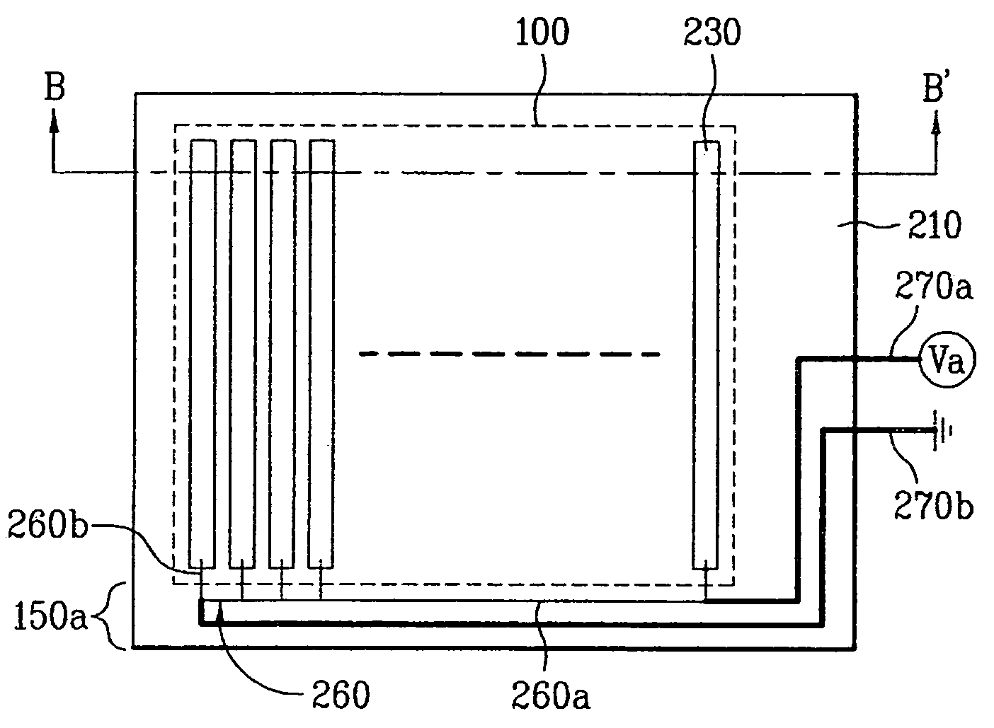
[0057]FIG. 6 illustrates a plan view of an upper substrate of a digital resistive-type touch panel in accordance with principles of the present invention.

[0058]Referring to FIG. 6, a digital resistive-type touch panel according to a second embodiment of the present invention may differ from the aforementioned digital resistive-type touch panel according to the first embodiment of the present invention in that first end portions of the first plurality of patterned transparent electrodes 230 shown in FIG. 4A may be connected to each other to form a first transparent electrode pattern 230a. Further, according to the second embodiment of the present invention, the power source voltage Va and a ground voltage GND may be applied to opposing ends of the first transparent electrode pattern 230a via power lines 270a and 270b.

[0059]In one aspect of the present invention, the first transparent electrode pattern 230a may be formed by connecting the respective first end portions of the first pl...

third embodiment

[0060]FIG. 7 illustrates a plan view of an upper substrate of a digital resistive-type touch panel in accordance with principles of the present invention.

[0061]Referring to FIG. 7, a digital resistive-type touch panel according to a third embodiment of the present invention may differ from the digital resistive-type touch panel according to the first embodiment of the present invention in that the main line 260a of the first signal line 260 shown in FIG. 4A may be formed in a tortuous pattern 260a. By providing the tortuous main line 260a, the length of conductor between adjacent ones of the first plurality of patterned transparent electrodes 230 may be increased. In one aspect of the present invention, the main line 260a may be formed of a metal material having an electrical resistance less than a material such as ITO.

[0062]According to principles of the present invention, use of the digital resistive-type touch panel is advantageous because dimensions defined where the patterned t...


PUM


Abstract

A digital resistive-type touch panel includes first and second transparent substrates opposing each other; a plurality of first transparent electrodes extending along a surface of the first transparent substrate; a plurality of second transparent electrodes extending along a surface of the second transparent substrate, wherein the first and second transparent electrodes cross each other; a first signal line for dividing an applied voltage and applying unique voltages to respective ones of the first transparent electrodes; and a plurality of second signal lines connected to respective ones of the plurality of second transparent electrodes.

Description

[0001]This application claims the benefit of the Korean Application No. P2002-72351 filed on Nov. 20, 2002, which is hereby incorporated by reference for all purposes as if fully set forth herein.BACKGROUND OF THE INVENTION[0002]1. Field of the Invention[0003]The present invention relates to digital resistive-type touch panels. More particularly, the present invention relates to a digital resistive-type touch panel having an increased ratio of viewing area to dead space.[0004]2. Discussion of the Related Art[0005]Information devices such as personal computers, mobile transmission devices, etc., use a variety of input devices such as keyboards, mice, digitizers, etc., to effect textual and other graphic processes. As the demand for information devices that are mobile and simple to use continues to increase, research into replacing relatively large input devices such as keyboards and mice has been performed to develop input devices that are easier to carry, and simpler to operate, tha...

Claims


Application Information

Patent Timeline
Patent Type & Authority Patents(United States)
IPC IPC(8): G06F3/041G06F3/042G06F3/043G06F3/045G06F3/033G06F3/03
CPCG06F3/045G06F3/03
Inventor HONG, HEE JUNGPARK, HEE JEONG
Owner LG DISPLAY CO LTD
Why Eureka
Try Eureka