Dynamic radiation therapy simulation system

a radiation therapy simulation and dynamic technology, applied in the field of simulation of radiation therapy, can solve the problems of distorted fluoroscopic image of patients, no known commercial system is capable of dynamic simulation, and conventional simulation systems cannot handle static treatment regimes, etc., and achieve the effect of more accurate image comparison

Inactive Publication Date: 2008-03-25
THE BOARD OF TRUSTEES OF THE UNIV OF ARKANSAS
View PDF7 Cites 151 Cited by
  • Summary
  • Abstract
  • Description
  • Claims
  • Application Information

AI Technical Summary

Benefits of technology

[0011]The present invention combines both hardware and software. The primary hardware component, other than conventional computer systems, is a respiration phase indicator. The patient's respiration causes changes in the position and shape of the tumor and the surrounding tissue. By turning the beam on-and-off based on the phase of the patient's respiration cycle, a more accurate treatment of the tumor is possible. The respiration phase indicator of the present invention uses a belt about the chest of the patient to measure changes in the circumference of the chest. The changes in the circumference are indicated by linear changes in the position of a radio-opaque indicator. The respiration phase indicator of the present invention therefore differs from the prior art in that changes in circumference of the chest are measured rather than simple up-and-down movements of the chest and the indicator (since it is radio-opaque) appears directly in the fluoroscopic images of the patient.
[0013]Displaying each segment of dynamic treatment beams on top of real-time fluoroscopic image sequences allows the physician-physicist team to verify that all beamlets are aiming at right target prior to real treatment. To address the movement of tumors and surrounding tissues due to respiration, the respiration cycle indicator allows the simulation of respiratory gated IMRT treatment. Automated distortion correction of image intensifier and image registration enable more accurate image comparison. The present invention can overlay reference images, contours, block and MLC ports on the fluoroscopic image. It can help position the patient by fusing reference images with the real-time fluoroscopic image. It can acquire sequential simulation images for a number of respiratory cycles to study organ motion and determine the size of the margin. It can also do filmless simulation with the help of DICOM connectivity.

Problems solved by technology

First, no known commercial system is capable of dynamic simulation.
Conventional simulation systems can only handle static treatment regimes.
The fluoroscopic image of the patient is typically distorted in the image intensifier.

Method used


Image

  • Dynamic radiation therapy simulation system
  • Dynamic radiation therapy simulation system
  • Dynamic radiation therapy simulation system

Examples


Embodiment Construction

[0029]With reference to FIGS. 1-14, the preferred embodiment of the present invention may be described.

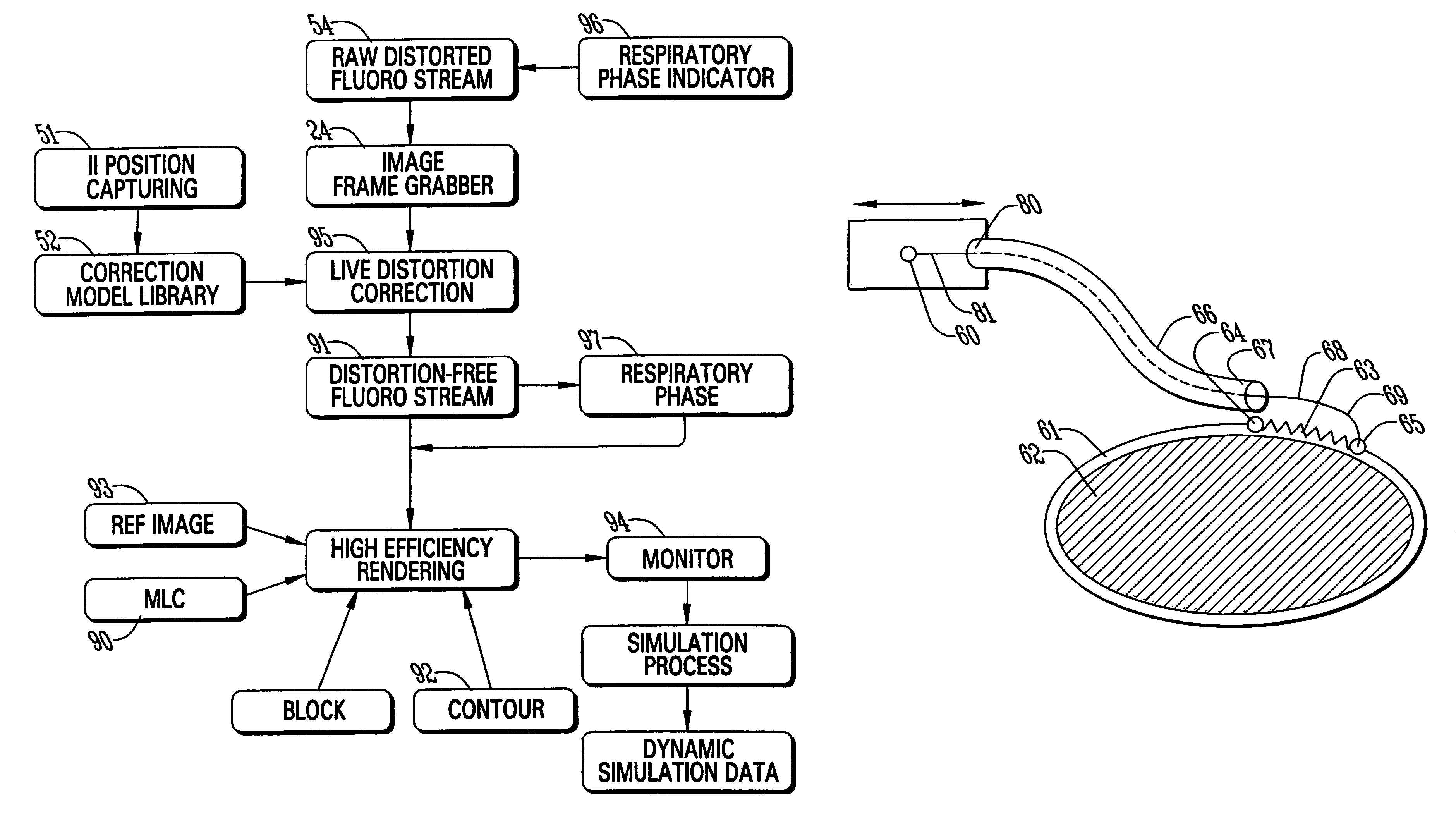
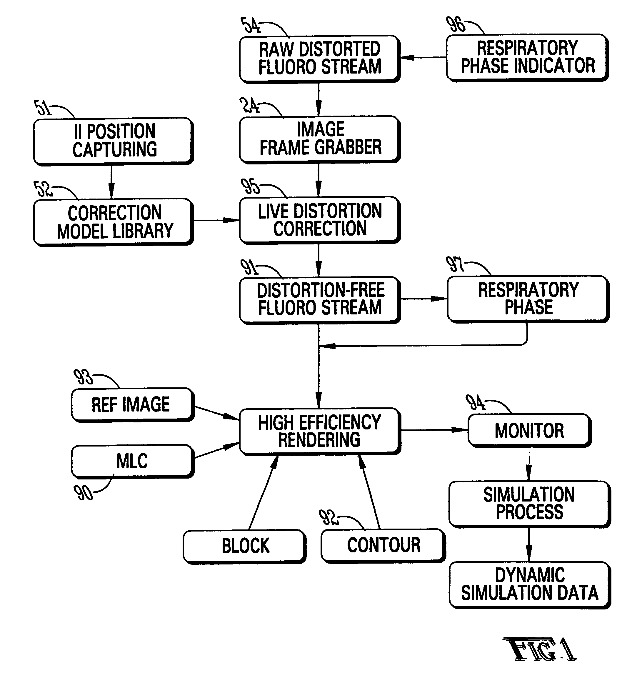
[0030]The ideal goal of image-guided high-precision radiation therapy is to deliver a highly conformal dose to even a moving tumor while sparing surrounding normal tissues. Such a goal is becoming more practical with the merging of treatment planning technologies based on four-dimensional CT, tumor tracking technologies and respiration gating systems. Consequently new treatment simulation systems are needed to accommodate changes in treatment planning and delivery of four-dimensional image guided radiation therapy (4DIGRT) and respiration-gated intensity-modulated radiation therapy (RGIMRT).

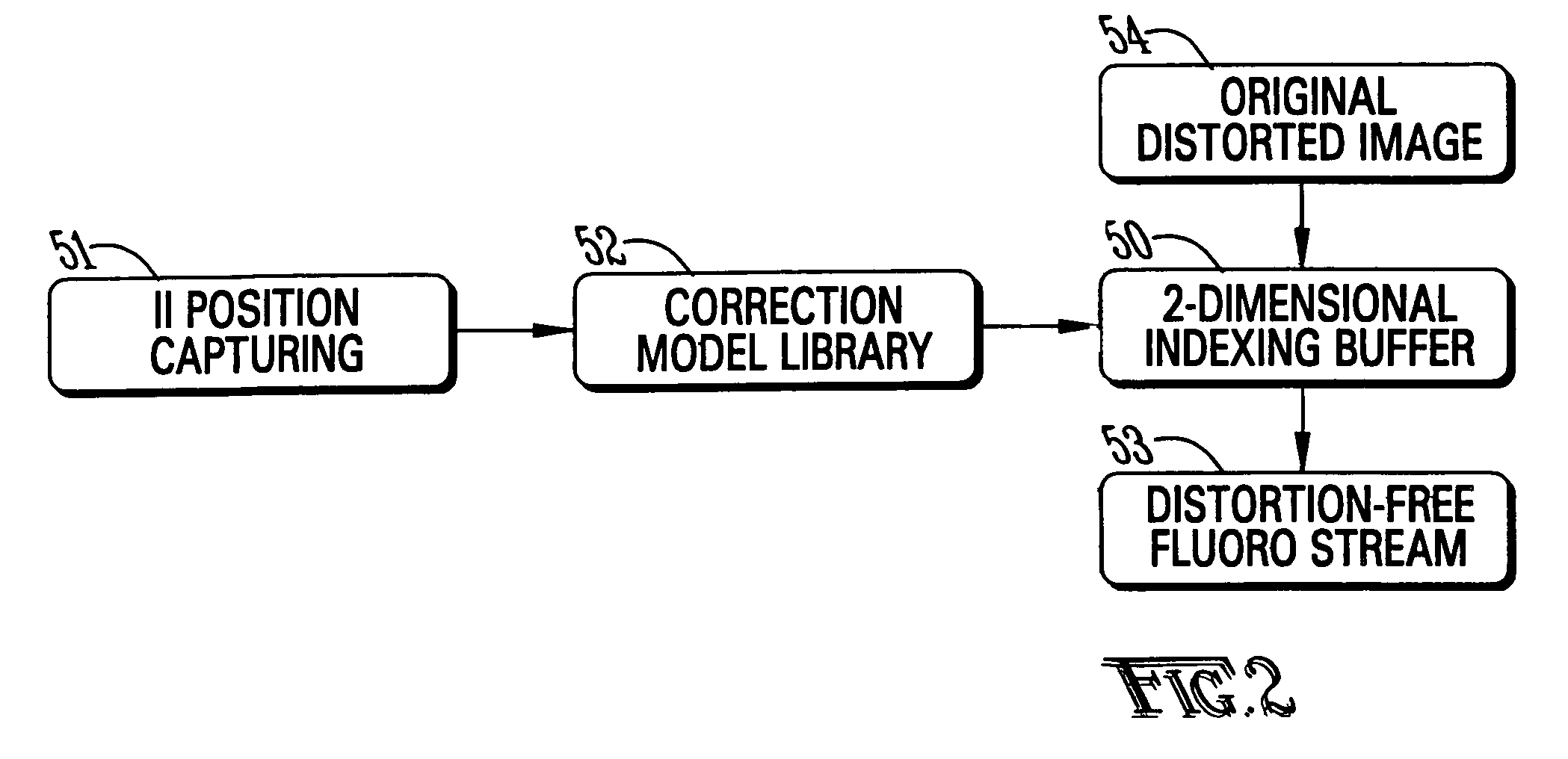
[0031]The software of the present invention interfaces with a conventional simulator 100 operating in the fluoroscopic mode. A frame grabber is used to obtain live images from the image intensifier (II). The patient's treatment plan, including DRR's, beams, contours and MLCs can be imported into...


PUM


Abstract

A system for dynamic treatment simulation for radiotherapy. Software is implemented on a computer system to perform dynamic simulation by displaying every segment of dynamic treatment beams on top of real-time fluoroscopic image sequences. Automated distortion correction of the fluoroscopic image due to the image intensifier is performed in real-time. A respiration phase indicator measures changes in circumference of the patient's chest through the movement of a radio-opaque marker that appears directly in the fluoroscopic images of the patient.

Description

CROSS-REFERENCE TO RELATED APPLICATIONS[0001]Not applicable.STATEMENT REGARDING FEDERALLY SPONSORED RESEARCH OR DEVELOPMENT[0002]Not applicable.BACKGROUND OF THE INVENTION[0003]1. Field of the Invention[0004]The present invention relates to the simulation of radiation therapy and in particular, to a system which is able to simulate dynamic treatment regimes.[0005]2. Brief Description of the Related Art[0006]Fractionated conformal radiotherapy, such as intensity-modulated radiotherapy, that employs computer-controlled multi-leaf collimators, requires accurate beam placement in reference to the patient's anatomy. Beam placement and beam apertures are defined based on either CT simulation (beam's eye view planning) or conventional RF simulation. After the completion of the treatment plan, the treatment fields and their corresponding blocks (defined either by the multi-leaf collimator (MLC) or cerroband block) need to be verified prior to the treatment both for isocenter placement and f...

Claims


Application Information

Patent Timeline
Patent Type & Authority Patents(United States)
IPC IPC(8): A61N5/10
CPCA61B5/0816A61N5/1049G01N23/223A61B6/541A61N5/1037G01N2223/076A61N2005/1061A61N2005/1062A61N5/1067
Inventor YAN, YULONGWENG, XUEJUNRATANATHARATHORN, VANEERATPENAGARICANO, JOSE
Owner THE BOARD OF TRUSTEES OF THE UNIV OF ARKANSAS
Why Eureka
Try Eureka