Valve

Inactive Publication Date: 2008-04-01
G A APOLLO
View PDF16 Cites 87 Cited by
  • Summary
  • Abstract
  • Description
  • Claims
  • Application Information

AI Technical Summary

Benefits of technology

[0034]It will be appreciated that the safety lock prevents undesired movement of the actuation means. Accordingly, this lock acts as a warning indicator to a user. If the lock device is engaged while the valve is being attached to the opening of the vessel and/or pipe and remains locked while the sealed entry side of the valve is being resterilised, the user knows definitiv

Problems solved by technology

A major challenge to these industries is the need to demonstrate accurately and reproducibly that sterility is achieved and maintained throughout production lines within a plant.
Acceptable standards can be difficult to be met when a substance is transferred from one sterile location to another sterile location by non direct means.
However during connection of the connecting valve to the first sterile location, the external connecting surface of the connecting valve is exposed to the atmosphere and sterility of the valve is compromised.
Alternative methods of substance transfer suffer from similar problems.
However, a major disadvantage of this technique is that the vessel must be empty before sterilisation.
Again a major disadvantage associated with this system is that the bag must be empty before sterilisation.
However despite the necessity to undertake these actions in a designated ‘Grade A’ zone, there is an increased risk of contamination due to the

Method used


Image

  • Valve
  • Valve
  • Valve

Examples


first embodiment

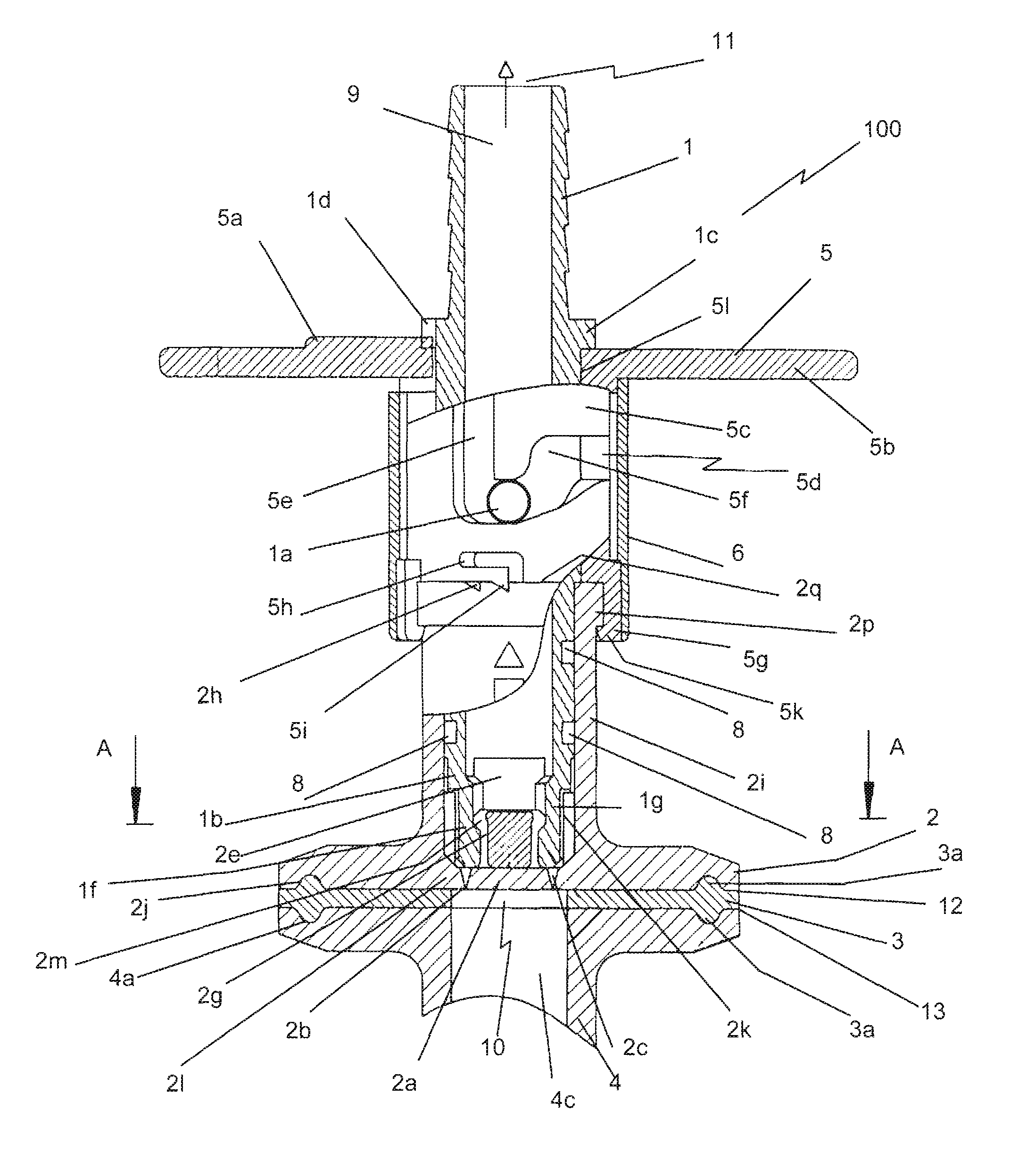
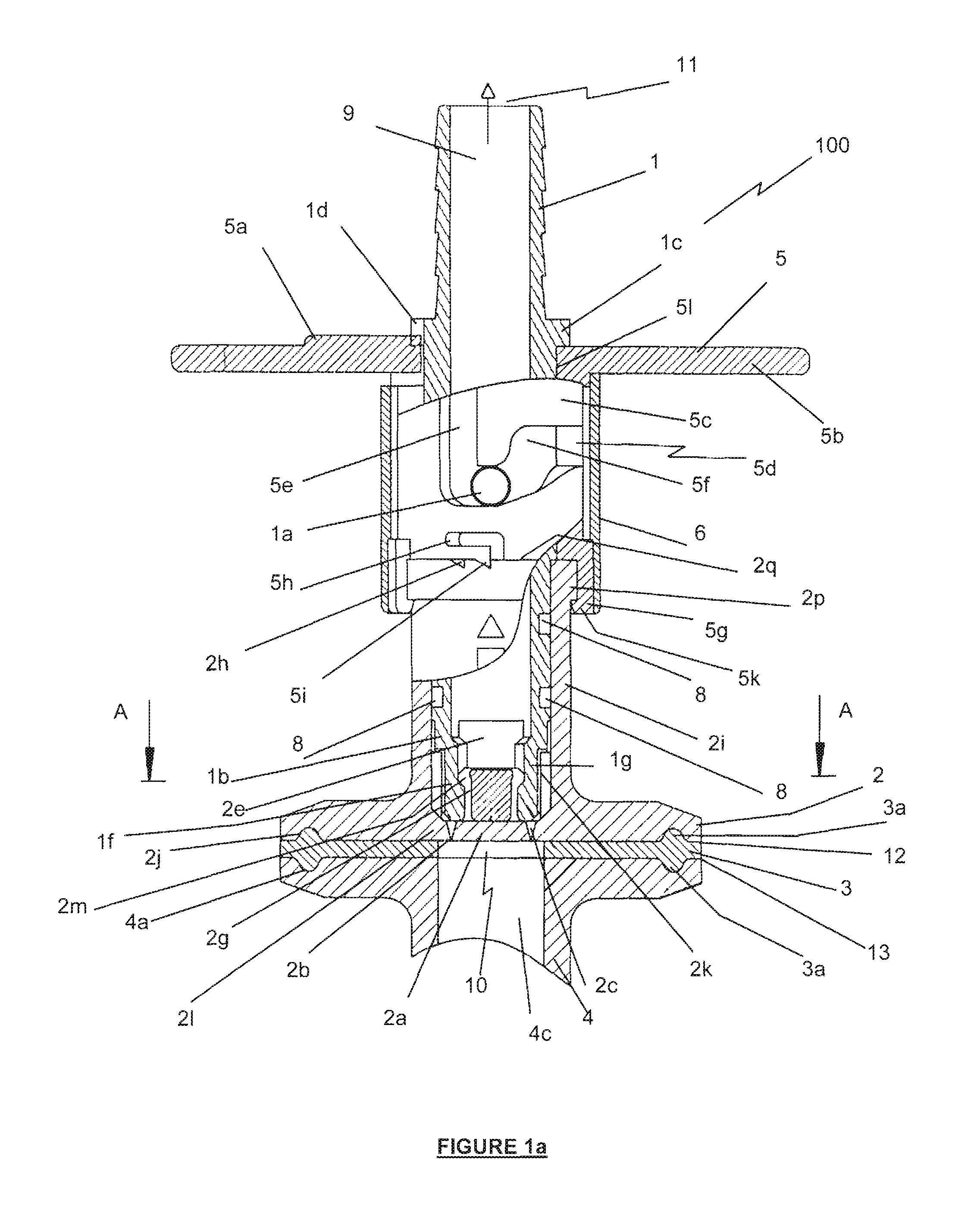
[0068]Referring initially to FIGS. 1a to 1k and FIG. 9, there is shown a single-use valve 100 according to the invention in its closed state. Valve 100 comprises a housing 2 having a bore for receiving a hollow piston 1. Valve 100 has an entry side generally designated 10 and an exit side generally designated 11. At the entry side, housing 2 is connectable to a vessel 4 so that the fluid paths of the opening 4c in vessel 4 and fluid path 9 of the valve 100 are in register. Each of the housing 2 and vessel 4 have corresponding mating surfaces 12, 13, which can be connected together in use in the manner described below. For this purpose, housing 2 is conveniently formed with a sleeve region 2i having at one end an outwardly extending flange 21, the base of the flange 21 comprising the mating surface 12. At its other end, sleeve region 2i is provided with a collar 2p, the end face 2q of which includes notches 2f, 2h, 2d. The purposes of the collar 2p and notches 2f, 2h, 2d will be desc...

second embodiment

[0092]FIGS. 4a and 4b show the valve 200 of the invention. Valve 200 operates as previously described in relation to the first embodiment. In this case valve 200 is coupled to an opening 40c of a separate vessel or pipe 40. The coupling surfaces 212, 413 of both the valve 200 and the opening 40c have a projecting rim 20a and 40a respectively encircling the outer edge of the surfaces. Each surface also has a groove 2j and 4a respectively encircling the circumference of the surface intermediate the seal 2a and the projecting rim. A washer 3 is placed between the two surfaces to provide a seal between them and the washer has complementary ring formations 30a sized and shaped to fit within the grooves in the coupling surfaces.

[0093]FIGS. 5a and 5b are views of a third embodiment of the valve 300 of the invention, which is a modification of the second embodiment. Valve 300 is adapted to connect at its exit side to an opening on a pipe or vessel in similar fashion to the connection at the...

fifth embodiment

[0098]FIGS. 10a, 10b and 10c are a plan view, a side section view and a sectional view of a single use valve 500 according to the invention. Valve 500 operates in the same manner as the previous embodiments of the valve, however the way in which the piston 1 is connected to the seal 2a is different. In this embodiment, the piston 1 and seal 2a are connected by means of a saw-tooth configuration 1c. The saw tooth fit also enables the seal 2a withstand pressures which are a multiple of the normal pressure of a sterilising fluid load without rupturing seal 2a at the junction 2b.


PUM


Abstract

A valve apparatus (100) for use in sterile fluid transfer or isolator systems has open entry (10) and exit (11) sides and a passageway (9) for fluid between the entry (10) and the exit (11) sides. The entry side (10) is connectable to an opening (4c) of a vessel or pipe (4) and the exit side (11) is connectable to downstream processing by means such as tubing, a vessel or a pipe. The entry side (10) includes a rupturable seal (2a) blocking the open entry side (10). Valve (100) also includes an actuator (5) attached to a piston (1) which moves within the valve (100), the piston being connected to the seal so that on movement of the piston, the seal is torn free from the entry side thereby allowing fluid gain entry to the valve (100) and to pass along the passageway (9) between the open entry (10) and exit (11) sides to downstream processing.

Description

CROSS-REFERENCE TO RELATED APPLICATIONS[0001]This application is the national stage filing under 35 U.S.C. §371 of PCT / US02 / 12924, filed Apr. 25, 2003, which claims priority to U.S. No. 60 / 375,747, filed Apr. 26, 2002 which is incorporated herein by reference.FIELD OF THE INVENTION[0002]The present invention relates to a valve apparatus and in particular to a valve apparatus useful in systems for the sterile transfer of fluids.BACKGROUND OF THE INVENTION[0003]Validation and accountability are vital in most scientific industries and especially so in the pharmaceutical and biotechnological industries. A major challenge to these industries is the need to demonstrate accurately and reproducibly that sterility is achieved and maintained throughout production lines within a plant. This must be done in a manner which meets the stringent requirements of regulatory bodies such as the United States FDA. Acceptable standards can be difficult to be met when a substance is transferred from one s...

Claims


Application Information

Patent Timeline
IPC IPC(8): F16K17/40A61M39/10A61M39/16A61M39/18A61M39/22F16K1/12F16K15/18
CPCA61M39/10A61M39/16A61M39/18A61M39/22F16K1/12F16K15/18A61M2039/1033A61M2039/222Y10T137/1692Y10T137/1767Y10T137/8225
Inventor LIEPOLD, GERHARDBIZER, DIETRICH
Owner G A APOLLO
Why Eureka
Try Eureka