Incontinence strip for treating urinary incontinence

a technology for urinary incontinence and incontinence strap, which is applied in the field of incontinence strap, to achieve the effects of preventing strap tearing, simple manner, and modifying flexibility

Inactive Publication Date: 2008-04-01
AESCULAP AG
View PDF41 Cites 67 Cited by
  • Summary
  • Abstract
  • Description
  • Claims
  • Application Information

AI Technical Summary

Benefits of technology

[0025]As stated above, the strap is preferably configured such that it may be drawn into the abdominal cavity, in particular, into the vicinity of the urethra, through the vaginal wall or abdominal wall, employing minimally invasive surgical techniques, i.e., without opening the abdominal cavity. In order to allow emplacing the strap at the right location in the body as simply as possible and in a manner that will be gentle to the patient, the strap is usually implanted using application aids. These application aids are usually attached to the ends of the strap and, in addition to the aforementioned shafts, may also consist of, for example, implantation needles or cords. The reinforcements in the vicinity of the attachment device on the incontinence strap according to the invention prevent tearing of the strap in the vicinities of the attachment devices due to the effects of tensioning by the application aids.
[0026]The incontinence strap is preferably reinforced in the vicinity of the attachment device by thermally bonding it to another material (In this conjunction, “thermally bonding” one or more materials to the strap means that one or more materials are thermally softened, or melted, and flow into the pores of the unmelted strap and harden there). The strap is thermally bonded to the sheath of the incontinence strap, in particular, thermally bonded thereto in that vicinity. Such thermal bonding of the strap to the sheath in the vicinity of the attachment device allows reinforcing the strap in that vicinity in a simple manner. Employing other weldable material in the process may also modify its flexibility.
[0027]In order to further reinforce the strap in the vicinity of the attachment device, additional, thermally bondable material, in particular, thermoplastic material, may be employed in the process. In the case of a preferred embodiment of an incontinence strap according to the invention, at least the sheath may be folded over in the vicinity of the attachment device and thermally bonded to the strap. This folding over may be accomplished in various manners. For example, the corners of the sheath may be folded over in order to configure the reinforcement in the form of an equilateral triangle, which has the benefit that the incontinence strap will then have tapered ends, and thus may be more easily drawn through tissue, while maintaining its orientation. In the case of another embodiment, the edges of the ends of the sheath may be folded over in order that the reinforcement will have a rectangular, or square, shape. In the case of yet another embodiment, both the corners and edges on the ends of the sheath may be folded over, which will yield particularly strong reinforcements in the vicinities of the attachment devices.
[0028]An embodiment where both the sheath and the ends of the strap are folded over, which will yield even greater strengthenings in those vicinities, will also be feasible.

Problems solved by technology

Mechanical irritations caused by the incontinence strap due to, for example, its surface texturing and / or pores, and / or irritations of biological origin occurring during resorption as a result of accelerated metabolic processes, may cause growth of new connective tissue that will yield a desired lifting, or supporting, of the urethra.

Method used


Image

  • Incontinence strip for treating urinary incontinence
  • Incontinence strip for treating urinary incontinence
  • Incontinence strip for treating urinary incontinence

Examples


Embodiment Construction

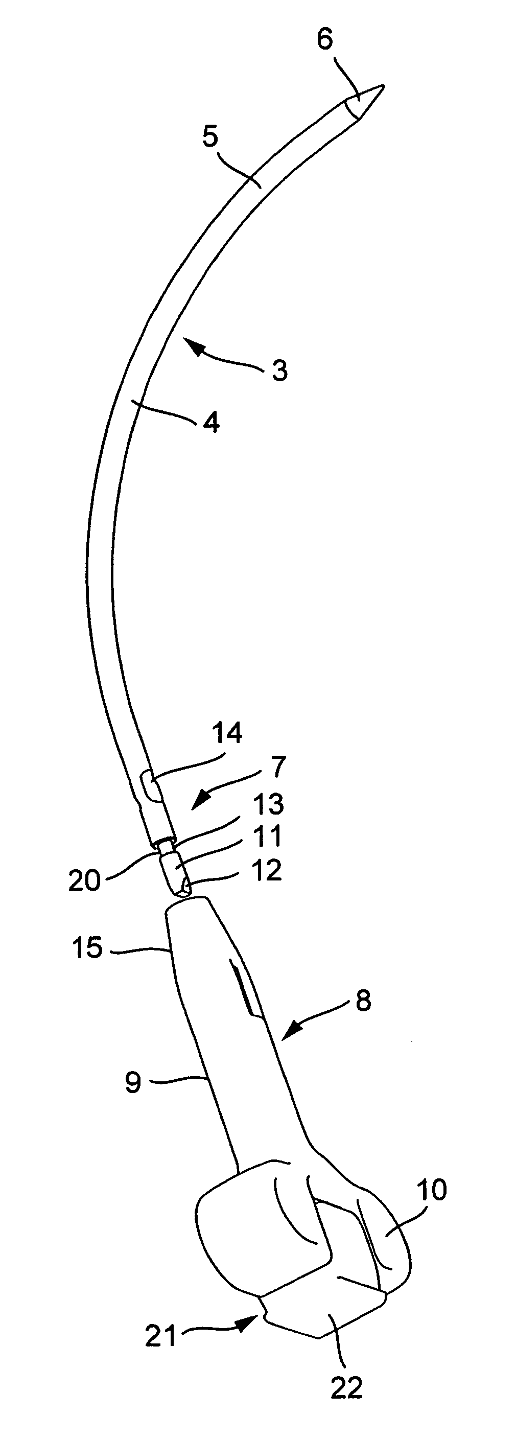
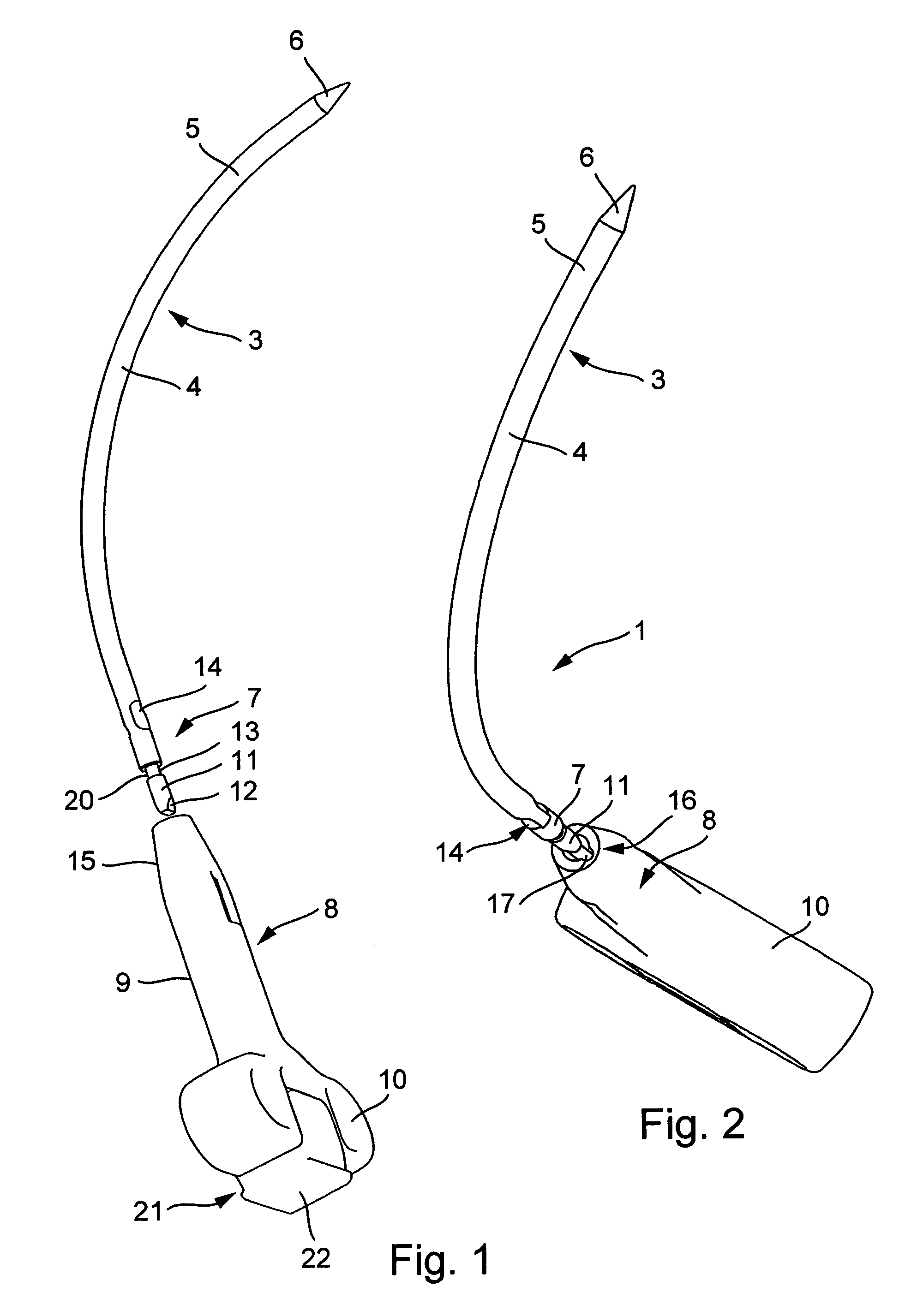
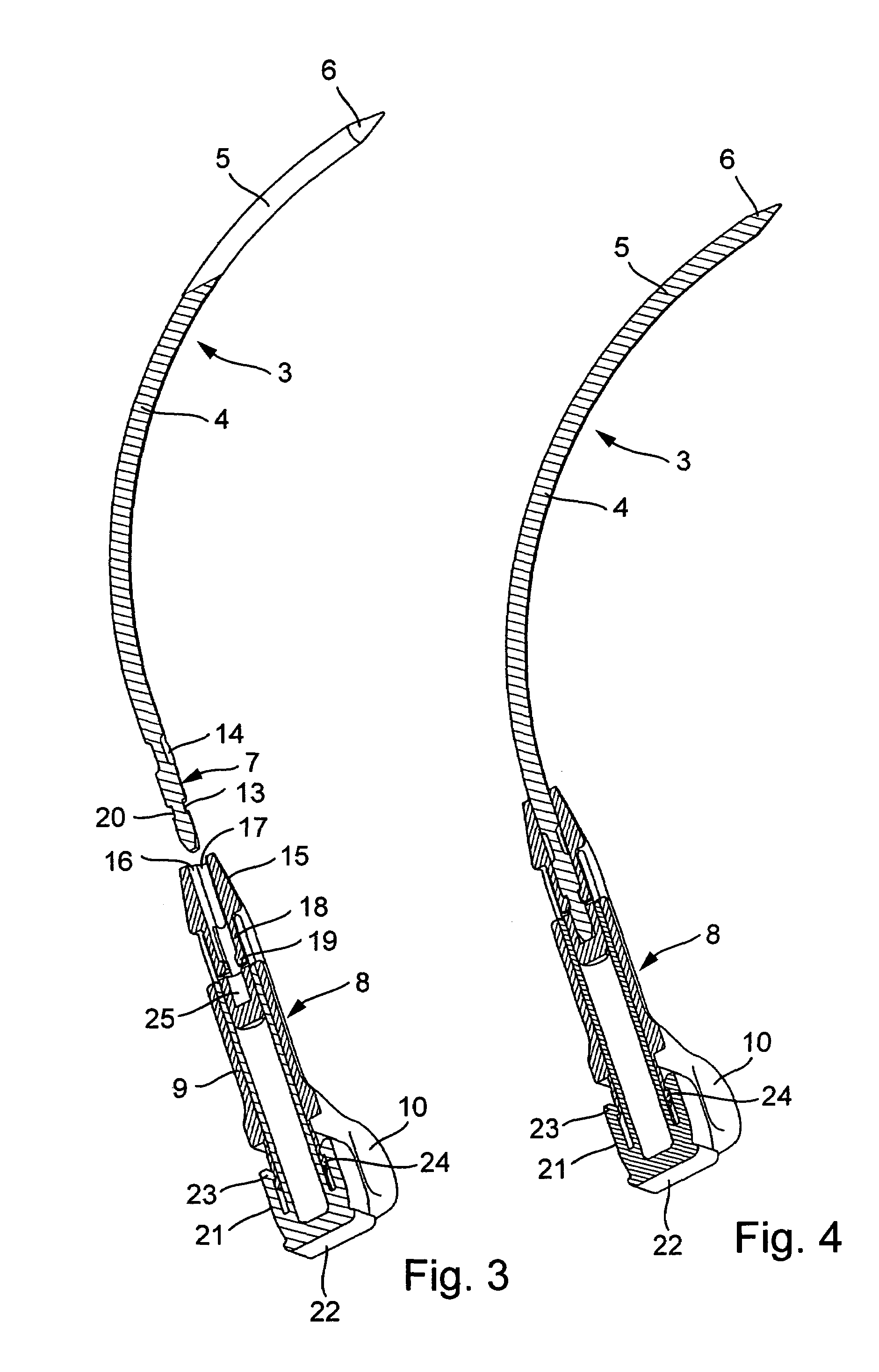
[0054]In the case of the embodiment of an instrument 1 for emplacing an incontinence strap 2 shown in FIGS. 1-9, a shaft for inserting the incontinence strap is provided in the form of a curved, solid, stainless-steel needle 3 in the form a curved, circular rod 4. The needle has a conical tip 6 on an insertion end 5. That may also be ground off at an angle such that the edge of the ground-off section lies on the inner side of the curvature. The tip of the needle is not sharp in order to prevent injuries to the abdominal organs when the incontinence strap is inserted. Since incisions in the abdominal wall and vaginal wall will, in any case, be made using other instruments, such as scalpels, the needle essentially acts as a guiding appendage only. The end of the needle opposite that bearing the tip 6 is configured in the form of an attachment end 7 and has devices for attaching it either to a grip 8, or to the incontinence strap 2.

[0055]The grip 8 consists of plastic or steel. It has ...


PUM


Abstract

The invention relates to a an incontinence strap (66) for treating urinary incontinence, in particular, urinary incontinence in females, that is configured such that it is flexible.

Description

BACKGROUND OF THE INVENTION[0001]1. Field of the Invention[0002]The invention relates to an incontinence strap for treating urinary incontinence, in particular, urinary incontinence in females.[0003]2. Description of Related Art[0004]Various operative methods and specially designed operating utensils and implants have been developed for remedying urinary incontinence. Several operative methods require opening the abdominal cavity in order to introduce items, similar to prostheses, that either encircle the urethra in the vicinity of the neck of the bladder or press against it from above or below (cf. WO 00 / 18319, WO 90 / 01016, WO 91 / 00069, U.S. Pat. No. 4,709,690, and WO 85 / 02993).[0005]The so-called “plastic rein” was developed in the 1960's. In the case of this particular device, a strap that is wrapped around the underside of the urethra in order to raise the bladder, along with the neck of the bladder, which will be particularly helpful if the bladder has sagged, is attached withi...

Claims


Application Information

Patent Timeline
Patent Type & Authority Patents(United States)
IPC IPC(8): A61F2/02A61B17/00A61B17/04A61B17/06A61F2/00
CPCA61B17/06109A61F2/004A61F2/0045A61B17/06004A61B17/06066A61B2017/0046A61B2017/00805A61B2017/0608
Inventor GOLDMANN, HELMUTODERMATT, ERICH K.WEIS, CHRISTINEWOELFLE, WERNERMELCHIOR, HANSJOERGABELE, WOLFGANG
Owner AESCULAP AG
Why Eureka
Try Eureka