Trouble diagnosis apparatus for supercharger of internal combustion engine

a diagnostic apparatus and turbocharger technology, applied in the direction of machines/engines, electrical control, instruments, etc., can solve the problems of difficult to determine an abnormality, inability to accurately determine the occurrence of an abnormality in the turbocharger, and mechanical abnormalities may occur in the turbocharger, so as to improve the accuracy of abnormal diagnosis

Inactive Publication Date: 2008-04-01
TOYOTA IND CORP +1
View PDF11 Cites 26 Cited by
  • Summary
  • Abstract
  • Description
  • Claims
  • Application Information

AI Technical Summary

Benefits of technology

[0016]It is an object of the present invention to provide an abnormality diagnostic apparatus for a supercharger of an internal combustion engine that improves the accuracy of abnormality diagnosis for the supercharger regardless of the structure of the first and second intake passages.

Problems solved by technology

As a result, a mechanical abnormality may occur in the turbocharger due to severe engine operation from harsh conditions or wear.
Therefore, it would be difficult to determine an abnormality.
Thus, the occurrence of an abnormality in the turbo charger cannot be accurately determined based on the difference between the intake pressures in the intake passages.

Method used


Image

  • Trouble diagnosis apparatus for supercharger of internal combustion engine
  • Trouble diagnosis apparatus for supercharger of internal combustion engine
  • Trouble diagnosis apparatus for supercharger of internal combustion engine

Examples


Embodiment Construction

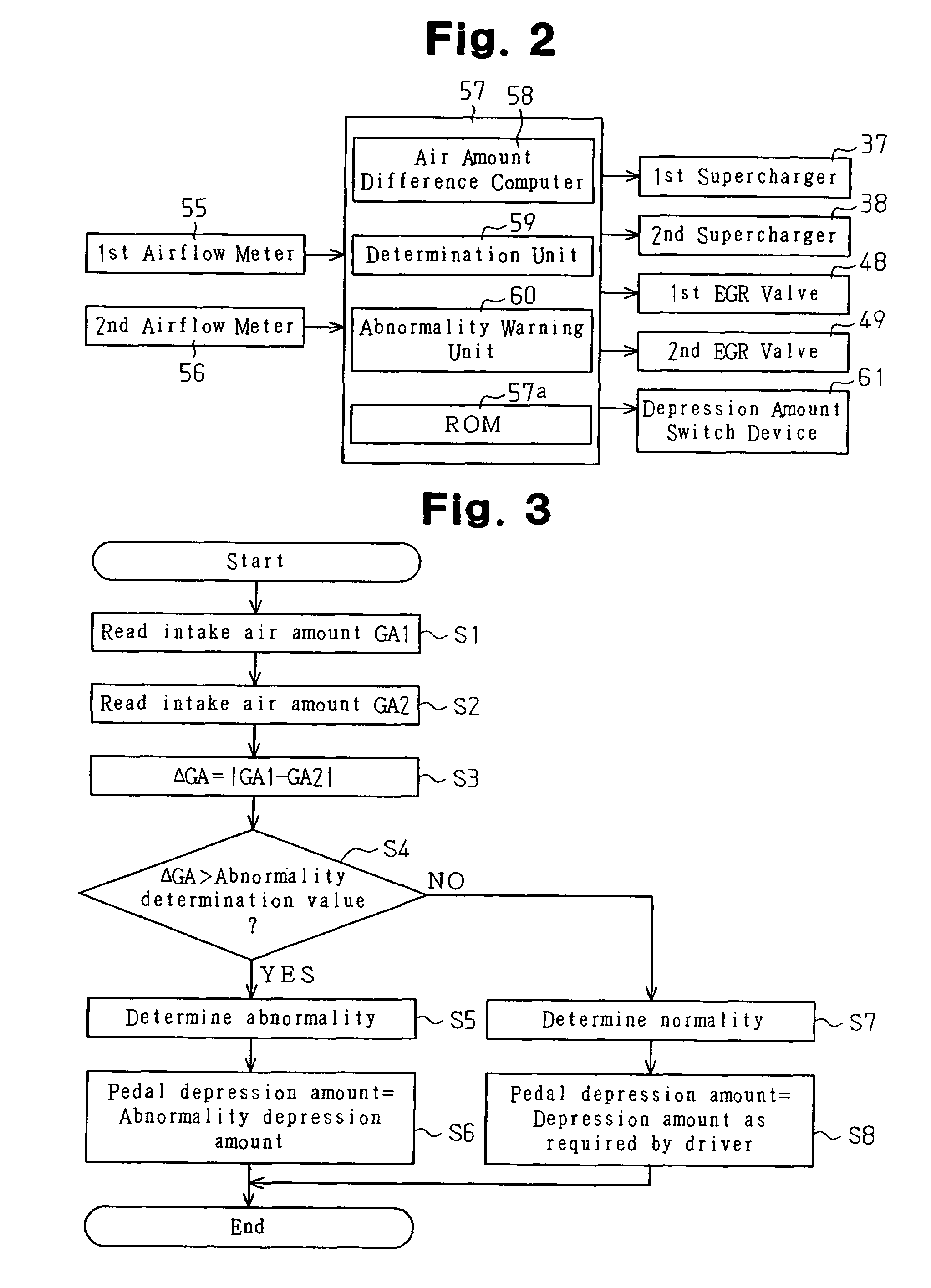
[0021]An embodiment of the present invention will be described hereafter with reference to the drawings.

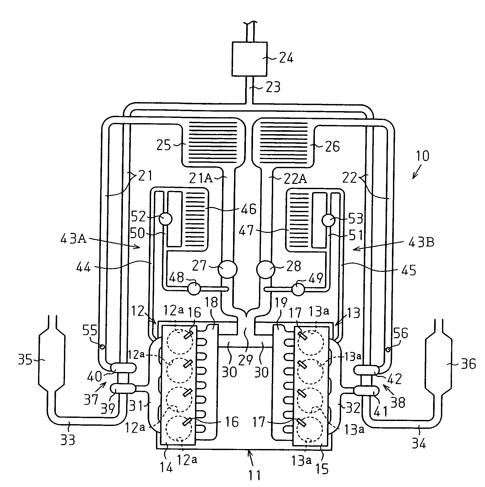
[0022]As shown in FIG. 1, a cylinder block 11 of an internal combustion engine 10 includes a first cylinder bank 12, which has a plurality of cylinders 12a arranged in a single line, and a second cylinder bank 13, which also has a plurality of cylinders 13a arranged in a single line. The cylinders 12a form a first cylinder row, and the cylinders 13a form a second cylinder row. The first and second cylinder banks 12 and 13 are arranged at a predetermined angle with respect to each other so as to have a V-shape when viewed in the direction in which the cylinders 12a and 13a are arranged. First and second cylinder heads 14 and15 are mounted on the cylinder block 11 respectively in correspondence with the cylinder banks 12 and 13.

[0023]Fuel injection valves 16 are attached to the first cylinder head 14 in correspondence with each cylinder 12a, and fuel injection valves 17 are attached...


PUM


Abstract

An internal combustion engine includes parallel first and second intake passages, and the intake passages respectively include first and second superchargers. A first airflow meter measures the intake air amount in the first intake passage. A second airflow meter measures the intake air amount in the second intake passage. An ECU obtains an air amount difference between the intake air amount measured by the first airflow meter and the intake air amount measured by the second airflow meter to compare the obtained air amount difference with a predetermined abnormality determination value. The ECU determines that an abnormality has occurred in one of the superchargers when the air amount difference exceeds the abnormality determination value. The abnormality determination of the superchargers is based on the air amount difference between the intake passages. This accurately determines the occurrence of an abnormality in the superchargers regardless of structure of the intake passages.

Description

FIELD OF THE INVENTION[0001]The present invention relates to a diagnostic apparatus for superchargers provided in each of a pair of intake passages in a V-type, horizontally opposed-type, or inline-type internal combustion engine.BACKGROUND OF THE INVENTION[0002]A V-type internal combustion engine includes a cylinder block having first and second cylinder banks arranged in a V-shaped manner. The cylinder block has first and second cylinder heads mounted on the first and second cylinder banks, respectively. Air is drawn into the cylinders of the first cylinder bank via a first intake passage and a first intake manifold. Air is also drawn into the cylinders of the second cylinder bank via a second intake passage and a second intake manifold. In such an internal combustion engine, the arrangement of first and second superchargers in the first and second intake passages to improve output is known in the art. Each supercharger uses the pressure of exhaust gas discharged from the internal...

Claims


Application Information

Patent Timeline
Patent Type & Authority Patents(United States)
IPC IPC(8): F02B39/16G06F19/00F02B37/007F02B29/04F02B37/00F02B37/02F02B37/12F02D21/08F02D23/00F02D41/00F02D41/18F02D41/22F02D45/00F02M25/07
CPCF01N13/107F02B29/0412F02B29/0418F02B37/007F02B37/12F02D41/0007F02D41/18F02D41/221F02M25/0711F02M25/0728F02M25/0732F02M25/0744F02M25/0748Y02T10/146Y02T10/144F02M26/08F02M26/24F02M26/25F02M26/38F02M26/42Y02T10/12
Inventor NARITA, YUJITAKAHASHI, YOSHIYUKIIMAI, TAKESHISUZUKI, HISANOBU
Owner TOYOTA IND CORP
Why Eureka
Try Eureka