Engineered glasses for metallic glass-coated wire

a technology of glass coating and engineering glasses, applied in the field of metal wire, can solve the problems of glass cracking during manufacture or after, the cooling rate employed by the taylor method is much too low for the production of metallic wire, and the cracking problem is particularly acu

Inactive Publication Date: 2008-04-08
DEMODULATION
View PDF14 Cites 7 Cited by
  • Summary
  • Abstract
  • Description
  • Claims
  • Application Information

AI Technical Summary

Benefits of technology

[0009]The present invention provides a method and means for producing metallic glass-coated wire directly from the melt. Metallic glass-coated wire products produced in accordance with the invention exhibit improved magnetic response in the presence of an applied magnetic field. The high signal amplitude and increased gating distance of these products make them excellent candidates for use in EAS applications.

Problems solved by technology

Cooling rates employed by the Taylor method are much too low for production of metallic wire having an amorphous atomic structure.
One of the problems with glass-coated wire produced by the '066 patent process is the tendency of glass to crack during manufacture or afterwards.
The cracking problem is particularly acute when the product is exposed to changing temperatures.
Another problem with the product produced by the '066 patent is its limited magnetic properties, for example low signal amplitude in the presence of an applied magnetic field.
The restricted magnetic properties make the '066 product a poor candidate for use in EAS applications.
Such restricted magnetic properties impose reduced gating distance, limiting tag detection in EAS applications, and can trigger false alarms or fail to alarm during use of the tag in retail anti-theft systems.
They also limit performance of the glass-coated wire product in other electromagnetic applications such as inductors, sensors, and transducers.

Method used


Image

  • Engineered glasses for metallic glass-coated wire
  • Engineered glasses for metallic glass-coated wire
  • Engineered glasses for metallic glass-coated wire

Examples


example 1

[0070]An ingot composed of an amorphous-forming alloy is prepared by loading the appropriate weights of constituent elements into a quartz tube that is sealed at one end. The other end of this quartz tube is connected to a pressure-vacuum system to allow evacuation and back-filling with Ar gas several times to ensure a low oxygen Ar atmosphere within the quartz tube. Next, the closed end of the quartz tube in which the elements reside is introduced into a high frequency induction heating coil. With the application of radio frequency (“r.f.”) power, the elements inside the tube are caused to heat and melt into a stirred, homogeneous alloy body. When the r.f. power is shut off, the alloy body is allowed to cool to room temperature in the Ar atmosphere. Once cooled, the same alloy body is inserted into the bottom of a vertically disposed glass tube, having 6 mm diameter, that is sealed at the lower end. The upper end of this glass tube is connected to a pressure-vacuum system to allow ...

example 2

[0075]Amorphous glass-coated wire is prepared by the procedure described in Example 1. The microwire has an Fe77.5B15Si7.5 amorphous alloy core that is under tensile stress. It has a glass coating consisting essentially of a medium expansion alkali borosilicate having an approximate composition:

[0076]

ConstituentWeight %SiO272B2O312Al2O37Na2O6K202CaO1Working Point1140°C.Annealing Pt.570°C.Elastic Modulus80GPaαgl (Annealing pt. - 25° C.)7.0 ppm °C−1.

The working point of this glass is at the low end of allowed temperatures since the liquidus temperature of the alloy is 1,230° C.

[0077]

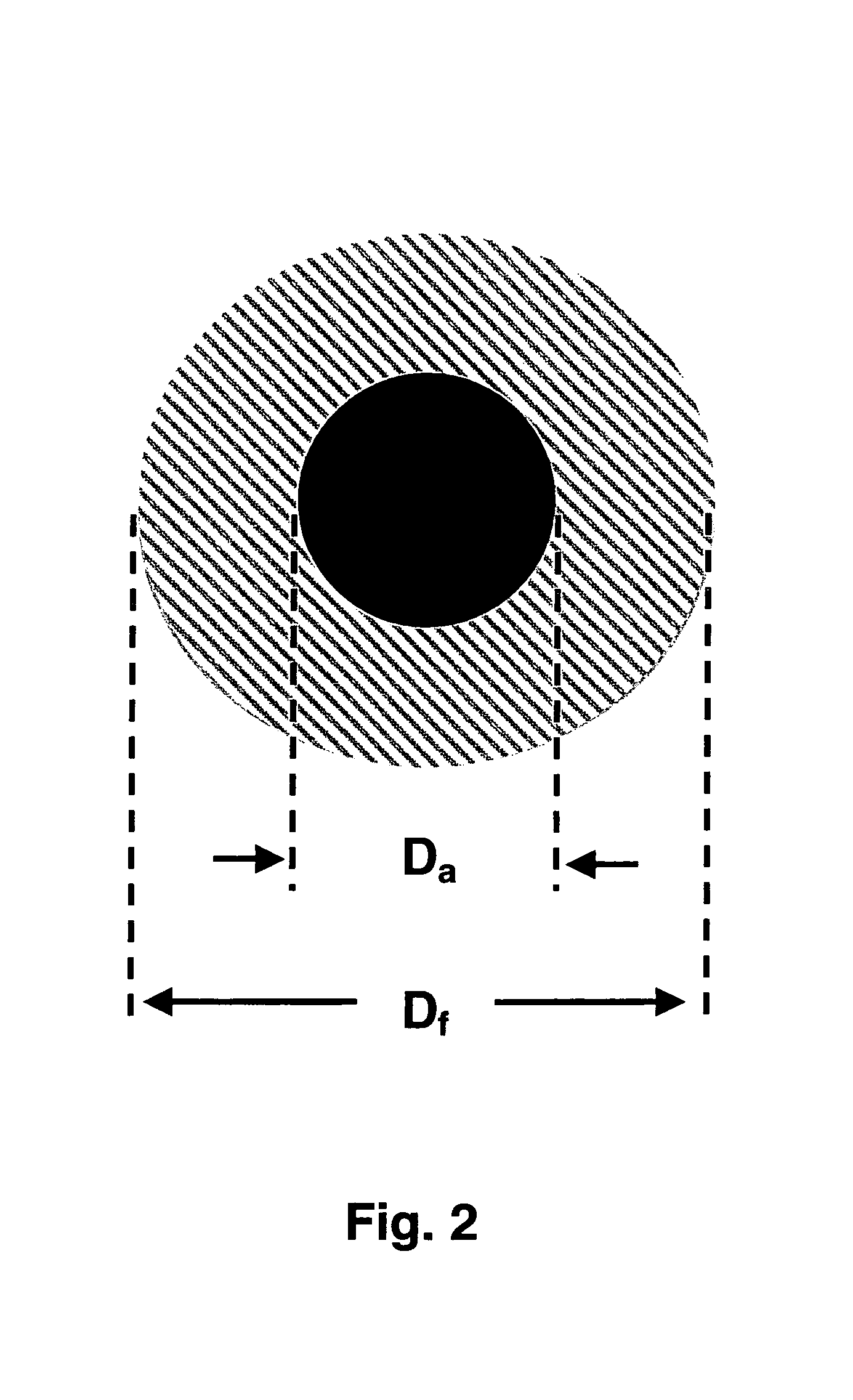
TABLE IVStresses in the metallic core and glass coatingas a function of the fiber geometry.αaαglEaEglppmppmdadfibσaσglGPaGPa° C−1.° C−1.μmμmMPaMPa4200808.07.05.025.0−14565200808.07.05.020.0−13796200808.07.010.015.0−5343

[0078]In this example the metallic core stress is small and can approach zero as the fiber diameter decreases while holding the metal diameter constant, or simultaneously.

example 3

[0079]Amorphous glass-coated wire is prepared using the procedure described in Example 1. The microwire has a Co66Fe4Ni1B14Si15 amorphous alloy core that is under low stress, since this alloy has nearly zero magnetostriction. Components of the glass-coated wire are described below:

Glass

[0080]Soda-lime silicate container glass—approximate composition:

[0081]

ConstituentWeight %SiO272B2O3—Al2O31Na2O14K20—CaO10MgO3Working Pt.1,035°C.Annealing Pt.560°C.Elastic Modulus70GPaα(Annealing pt. - 25° C. )10.3 ppm °C−1.

Alloy

[0082]

Liquidus1,080°C.E100GPaαa12.7 ppm °C−1.

[0083]Soda-lime silicate glass works well for this alloy as it has a lower working range, consistent with the low liquidus temperature of Co66Fe4Ni1B14Si15. Furthermore, the thermal contraction coefficient more closely matches that of the alloy.

[0084]

TABLE VStresses in the metallic core and glass coatingas a function of the fiber geometry.αaαglEaEglppmppmdadfibσaσglGPaGPa° C−1.° C−1.μmμmMPaMPa71007012.710.315.020.0−688781007012.710....


PUM

PropertyMeasurementUnit
elastic modulusaaaaaaaaaa
diameteraaaaaaaaaa

Abstract

A metallic glass-coated wire is formed by drawing a hollow glass fiber from a container in which molten alloy is entrained and solidified. Interference stresses extant between the glass coating and the alloy core of the wire are produced by systematically controlling thickness and mechanical elastic properties of the glass. The interference stress is tailored by selection of glass thickness and chemistry to optimize wire drawing process conditions, such as drawing temperature and strain rate. In addition, the interference stress is especially tailored to assure physical integrity of the glass-alloy composite wire product. Local property variations along the wire length are minimized, facilitating production of discrete wire segments especially suited for use in EAS applications.

Description

[0001]This application claims the benefit of U.S. Provisional Patent Application No. 60 / 437,460, filed Jan. 2, 2003, entitled “Engineered Glasses For Metallic Glass-Coated Wire”.BACKGROUND OF THE INVENTION[0002]1. Field of the Invention[0003]This invention relates to metallic wire for electromagnetic applications such as electronic article surveillance (EAS); and more particularly to engineered glasses having in combination transverse geometric dimensions and mechanical properties that collectively impart superior mechanical integrity and magnetic properties to the glass-coated EAS wire.[0004]2. Description of the Prior Art[0005]Fine glass-coated metallic wire has been produced in a single step process without the use of quenching substrates.[0006]A two-staged process as described by Taylor (Phys. Rev. 23, (1924) 655) involves drawing the end of a heated glass tube that contains molten alloy into a 0.5 to 1 mm diameter glass-coated rod having a length of a foot or more. This glass-c...

Claims


Application Information

Patent Timeline
Patent Type & Authority Patents(United States)
IPC IPC(8): B32B15/00B32B17/00C03B37/026H01B1/02H01B3/08
CPCC03B37/026H01B1/02H01B3/08Y10T428/2949Y10T428/294Y10T428/2958Y10T428/2933
Inventor LIEBERMANN, HOWARD H.LACOURSE, WILLIAM C.O'KEEFE, JR., JAMES E.
Owner DEMODULATION
Why Eureka
Try Eureka