[0006]As a result of the two-part construction of the strain measuring element used from a carrier element and a displacement
transducer, and as a result of the special shape of the carrier element, which registers the strain over a great length of the component and projects it onto a small section of reduced cross section, on which the displacement transducer is arranged, the force-dependent deformation of the force-transmitting component is amplified. By means of the increase in the deformation of the carrier element achieved in this way in the region of the displacement transducer, the result is a corresponding increase in the electric output
signal from the displacement transducer. Thus, on a component which, for example, is designed appropriately strongly in order to accommodate a mechanical bending load, a tensile load superimposed independently of the bending load can be measured reliably.
[0008]A recess in the component, above which the strain section and the sections of the carrier element adjacent thereto are arranged, ensures the free mobility of the carrier element with respect to the component in the section between the fixing sections. As a result, the different lengthening of individual sections of the carrier element is reliably permitted. The arrangement of the strain measuring element on the base of a depression in the component protects said strain measuring element against mechanical damage. If the depression is configured in such a way that the strain measuring element is located in the region of the
neutral axis of the component, then the output
signal from the displacement transducer is independent of a bending load of the component. Simple reliable fixing results from
adhesive bonding of the fixing sections of the carrier element to the component. Toothing the fixing sections of the carrier element and corresponding opposite toothing on the component improve the strength of the connection.
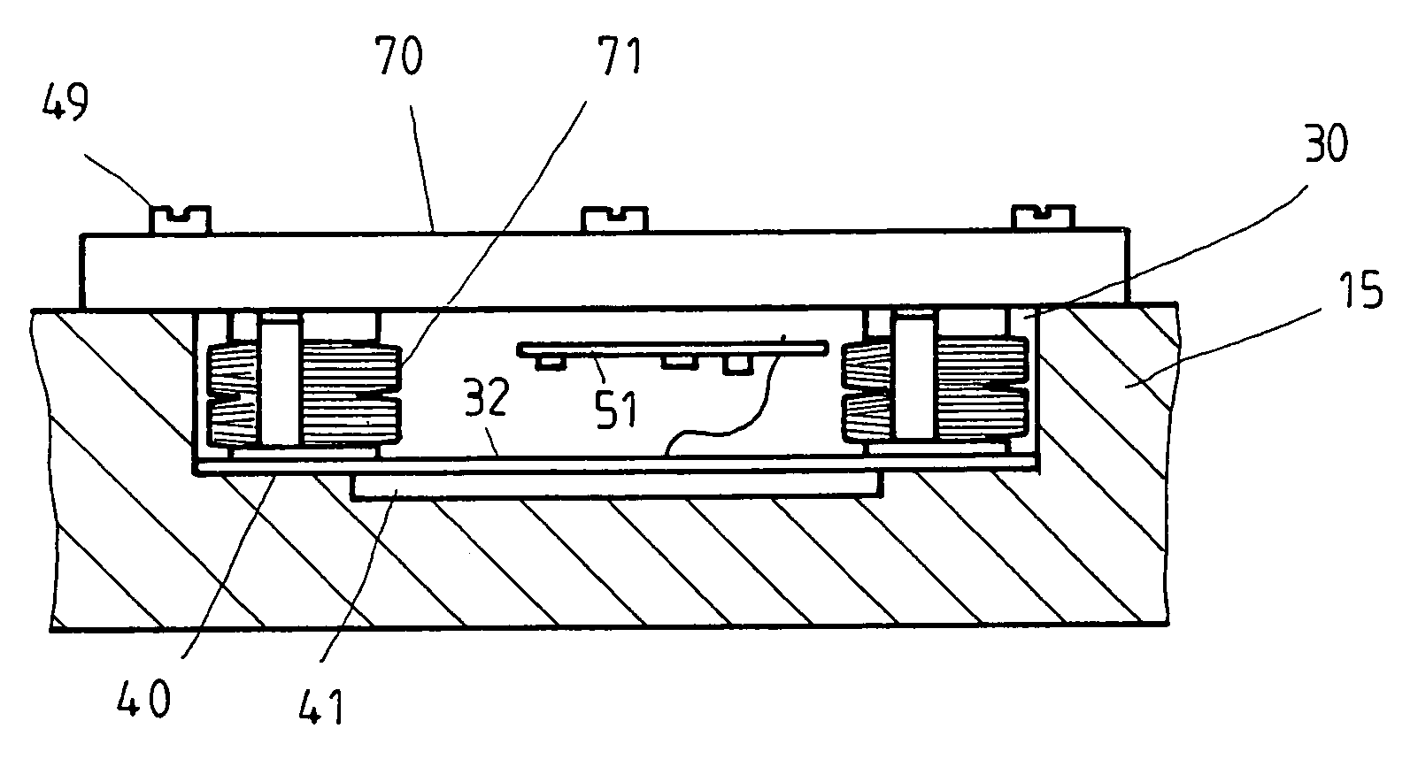
[0009]In a particularly preferred refinement, the fixing of the carrier element to the component is carried out via a clamped connection. As a result of the clamped connection, a frictional connection is made between carrier element and component. Thus, no external stresses caused by the fixing act on the strain measuring element, so that the strain measuring element measures the strain precisely and reliably without compensation. In addition, the provision of a clamped connection achieves overload protection for the strain measuring element. The clamped connection is preferably formed as a cover, which is held on the component and covers the depression, and pins clamped in between the cover and the carrier element. This achieves a simple clamped fixing which is capable of compensating for even relatively large fabrication tolerances during the fabrication of the depression. For this purpose, the length of the pins is preferably dimensioned such that they project beyond the edge of the depression, and the cover can be deformed plastically while maintaining residual elasticity.
[0010]The strain measuring element is preferably formed as a preassembled
structural unit to be inserted into a depression in the component and, in addition to the carrier element and the displacement transducer, has at least one cover to cover the depression, an electronic
amplifier circuit in order to amplify an
electric signal from the displacement transducer, and an elastic
potting compound provided between the cover and the carrier element and partly enclosing the strain measuring element. In this case, the side of the fixing sections facing a base of the depression is in each case not covered by the
potting compound. Such a
structural unit can be integrated into existing components with little effort on installation and makes the fabrication of force sensors easier. As a result of the integration of an
amplifier circuit in the preassembled
structural unit, transmission faults in the displacement transducer signal can be avoided. In addition, the
amplifier circuit provides a measured signal which is robust and suitable for motor vehicle use. The
potting compound protects the displacement transducer and the amplifier circuit against damage as a result of
weathering or penetrating
dirt.
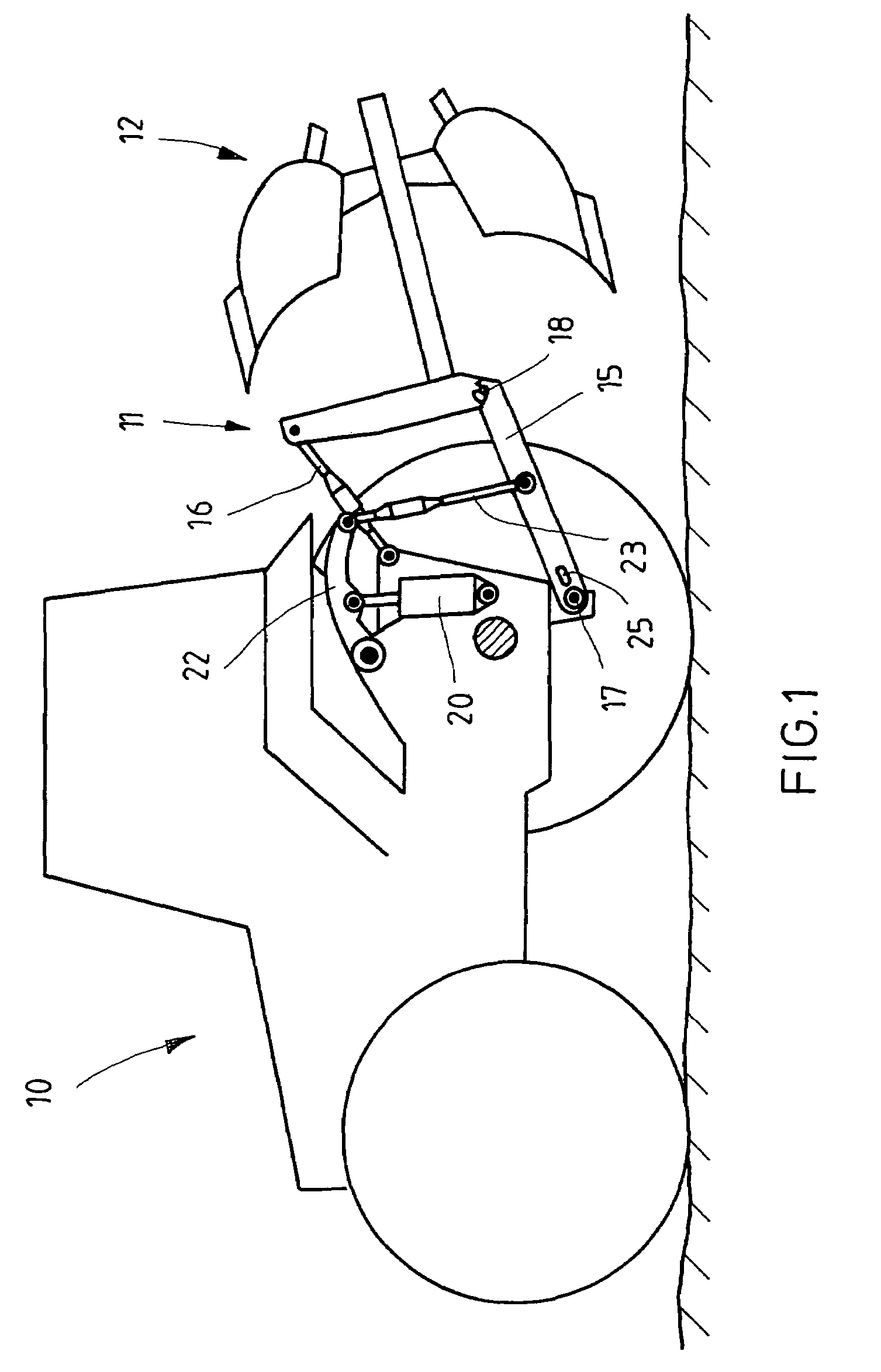
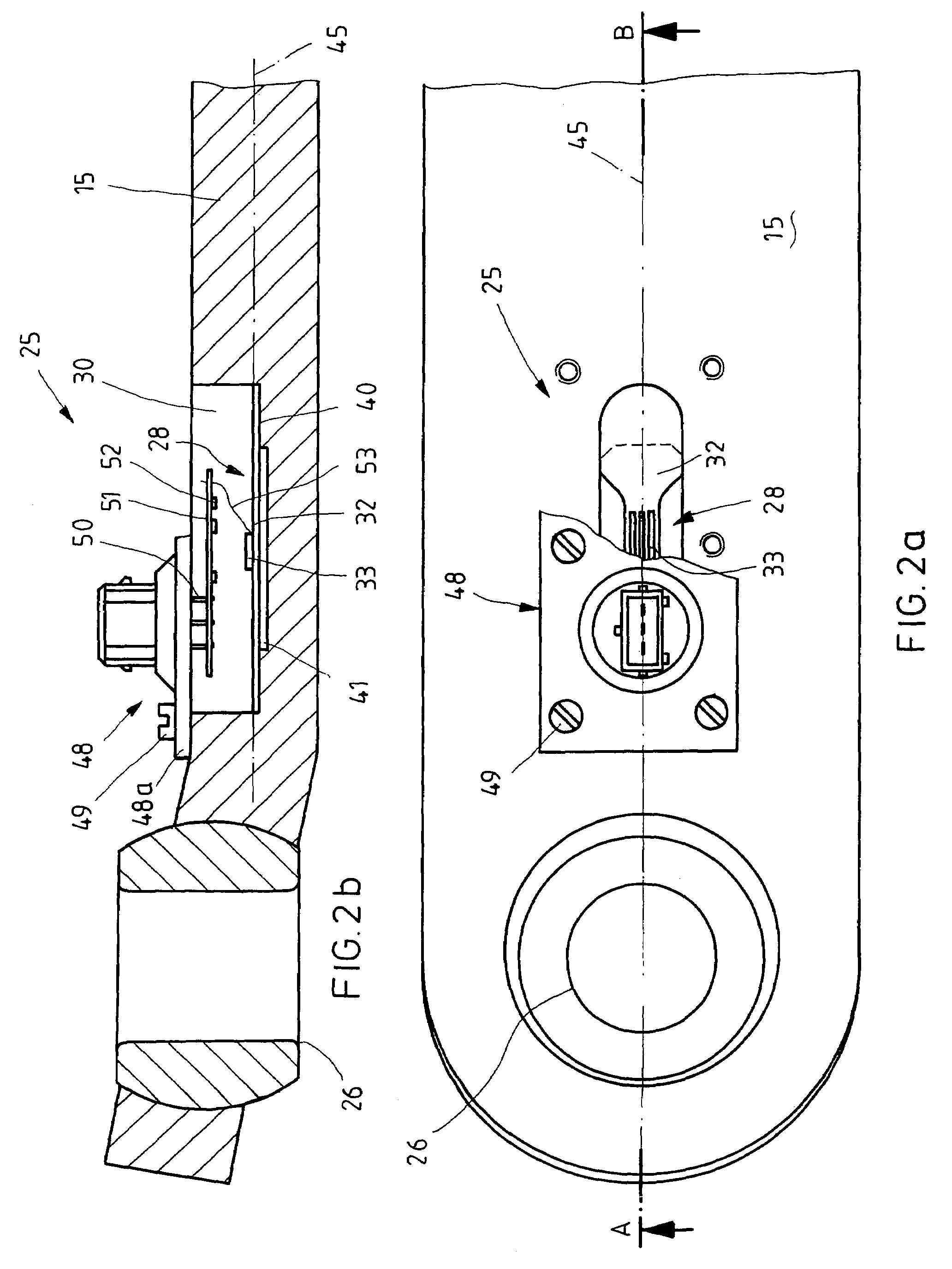
[0012]In order to measure the force with which an attachment held on an agricultural
machine acts on the latter, the strain measuring element is arranged in a depression of a lower link of a lifting mechanism, via which the attachment is held on the agricultural
machine. In this case, the depression for accommodating the strain measuring element is advantageously arranged in the vicinity of the
machine-side eye of the lower link. The component for holding the strain measuring element can also be formed as a link plate which, at each of its longitudinal ends, is provided with an eye to accommodate connecting elements, such as bolts. This configuration permits universal use of the force measuring apparatus according to the invention, for example also in the force flow of lifting appliances.
