Two stage sewage grinder pump

a sewage grinder and two-stage technology, applied in the direction of machines/engines, liquid fuel engines, gas current separation, etc., can solve the problems of inability to meet the needs of sewage treatment, etc., to achieve the effect of increasing the pressure of sewag

Active Publication Date: 2008-04-15
CRANE PUMPS & SYST INC
View PDF3 Cites 19 Cited by
  • Summary
  • Abstract
  • Description
  • Claims
  • Application Information

AI Technical Summary

Benefits of technology

[0011]In another aspect of the present invention, this is accomplished by providing a method for grinding and pumping sewage comprising: providing a motor having a shaft extending therefrom with a first stage impeller, a second stage impeller and a grinder attached thereto; operating the motor to rotate the attached impellers and grinder; introducing sewage into the grinder; grinding any solids contained in the sewage in the grinder; passing sewage from the grinder into the first stage impeller; increasing the pressure of the sewage by rotation of the first stage impeller; passing sewage from the first stage impeller into the second stage impeller; increasing the pressure of the sewage further by rotation of the second stage impeller; and discharging the pressurized sewage into a sewer system.

Problems solved by technology

However, in a hilly land area, in a below-grade setting, along long horizontal pipe runs or perhaps due to smaller-diameter piping restrictions, gravity often will not suffice.
However, one may require a larger HP centrifugal pump, an intermediate lift station, or a progressing cavity style pump when sewer system pressures or flow resistance exceeds the capabilities of a 2 HP centrifugal pump.
In residential applications, such systems are often unaffordable.
Unfortunately, wear items that readily fail at high pressures, such as that pump's wobble stator arrangement, are a significant disadvantage.
For example, design pressures can be readily exceeded and can remain high until an upset condition, such as excessive simultaneous operations following a power outage, or high infiltration caused by poor installation, is resolved.
However, a 2 HP residential centrifugal pump will have a significantly lower pressure limitation than a progressing cavity pump and is not suited for pressure sewer systems that achieve a total system head (distance pump is capable of lifting fluid) greater than 120 feet at the pump.
Thus, in a pressure sewer system where upset conditions produce high system pressures, both the progressing cavity and typical single-stage centrifugal grinder pumps lack relevant design efficiencies and possess limiting capabilities.

Method used


Image

  • Two stage sewage grinder pump
  • Two stage sewage grinder pump
  • Two stage sewage grinder pump

Examples


Embodiment Construction

[0037]FIG. 1 shows a basin 100 with a sewage grinder pump 10 according to the present invention installed within the basin The basin 100 has a sewage inlet 102 that receives sewage from a home, business or other source. Sewage flows into basin 100 through the sewage inlet 102 and drops to the bottom of the basin. Sewage grinder pump 10 sits within the basin 100 on pump supports 108, 109, attached to support wall 114, that raise the pump inlet 41 above the bottom of the basin. The pump discharge fluid conduit 80 is connected to sewage outlet 110. An isolation valve 104 with an extended operator handle 106 is provided to isolate sewage grinder pump 10 from the sewage outlet 110 to allow maintenance or removal of the sewage grinder pump.

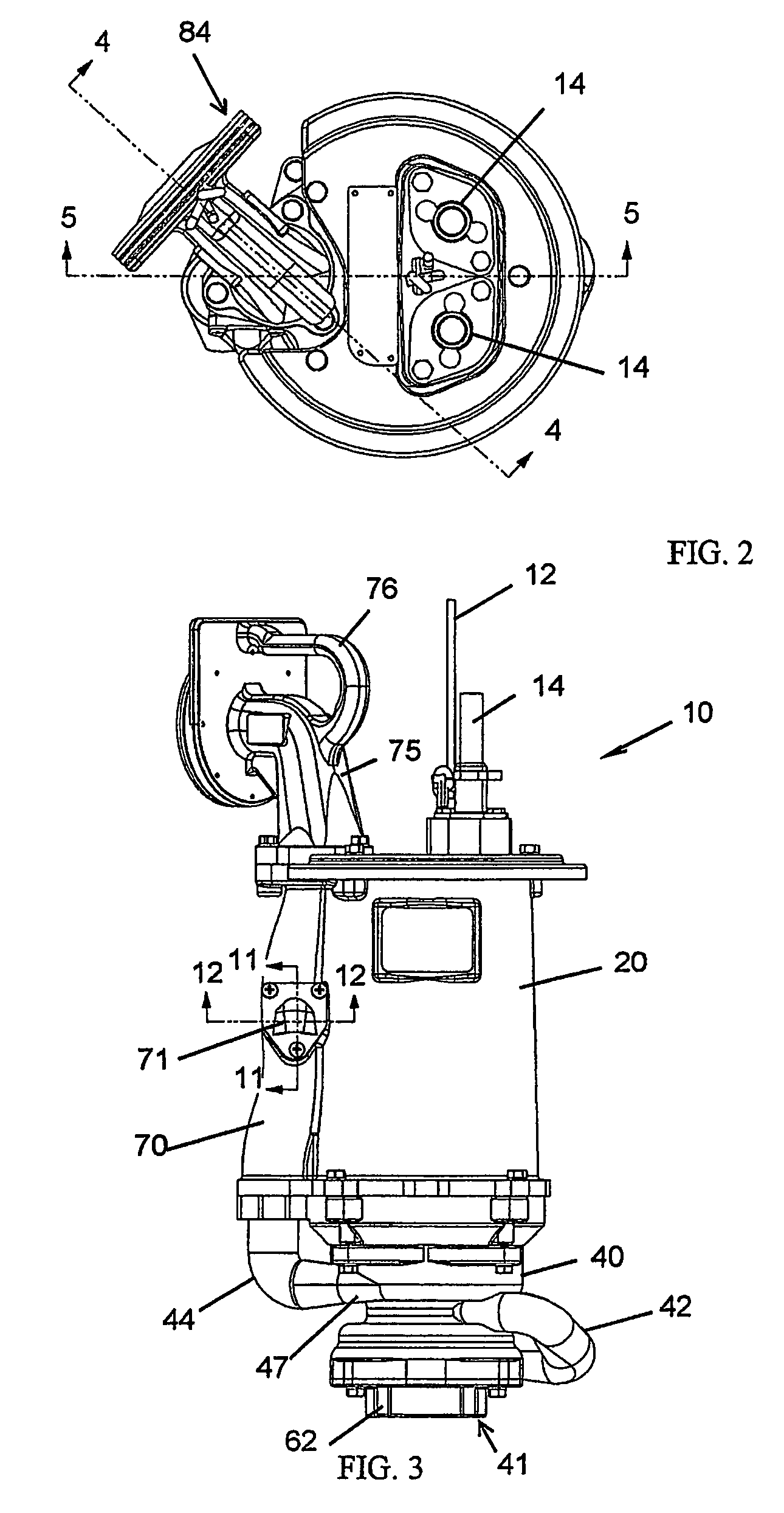
[0038]Sewage grinder pump 10 is further supported within basin 100 by a suspension cable 12. A pair of electrical conduits 14 provide electrical power and control signals to sewage grinder pump 10.

[0039]In operation, as the sewage level in basin 100 ris...


PUM

PropertyMeasurementUnit
speedaaaaaaaaaa
gravityaaaaaaaaaa
diameteraaaaaaaaaa

Abstract

A two-stage sewage grinder pump (10) having two impellers (30, 32) and a grinder (60) attached to the motor shaft (24). Preferably, both impellers are vortex impellers and are positioned between the grinder and the motor. The motor housing includes a discharge conduit (70) that is monolithic with the motor housing (20). An anti-siphon valve (71) is integral with the discharge conduit. An integral discharge flange (75) and check valve (78) are attached to the discharge conduit to connect the sewage grinder pump to a sewage outlet.

Description

[0001]This application is a national stage entry of PCT / lB2004 / 052100, filed Oct. 14, 2004, which designates the United States of America and which claims priority from provisional application 60 / 511,288, filed Oct. 14, 2003, the disclosure of which is hereby incorporated by reference.BACKGROUND OF THE INVENTION[0002]This invention relates generally to sewage grinder pumps and more particularly to two-stage high head low flow sewage grinder pumps.[0003]Many residential sewer systems use only the force of gravity to provide for discharging its wastewater into progressively larger sewer mains and ultimately to a dedicated treatment plant that is usually located in a low-lying area such that gravity can assist the flow of sewage. However, in a hilly land area, in a below-grade setting, along long horizontal pipe runs or perhaps due to smaller-diameter piping restrictions, gravity often will not suffice. In such situations, a lift-station or a stand-alone sewage ejector pump is required...

Claims


Application Information

Patent Timeline
Patent Type & Authority Patents(United States)
IPC IPC(8): B02C23/36B02C1/00C02FE03F5/22F04D1/06F04D7/04F04D9/00F04D29/42F04D29/60
CPCE03F5/22F04D1/06F04D7/045F04D9/008F04D29/426F04D29/606F04D29/607
Inventor GUTWEIN, GREGORY J.HOLDER, DONALDKOWALAK, MARK P.ORDWAY, BRUCE B.
Owner CRANE PUMPS & SYST INC
Why Eureka
Try Eureka