Apparatus and method for deploying geotextile tubes

a technology of geotextile tubes and apparatus, which is applied in the direction of piers, buttress dams, and groynes, etc., can solve the problems of increasing the possibility of damage to the beach from erosion, increasing the possibility of rolling, and abrasion of the filaments or yarns of the container

Inactive Publication Date: 2008-04-15
BRADLEY INDAL TEXTILES
View PDF36 Cites 31 Cited by
  • Summary
  • Abstract
  • Description
  • Claims
  • Application Information

AI Technical Summary

Benefits of technology

[0009]The present invention recognizes and addresses the foregoing disadvantages and others, of prior art constructions and methods. Accordingly, it is an object of the present invention to provide an improved method of stabilizing and positioning a geotextile tube or container.
[0010]It is a more particular object of the present invention to provide an improved cradle or foundation to assure the desired alignment of a geotextile container prior to the filling of the container with fill material of a solid nature.
[0011]It is a further object of the present invention to provide an improved cradle or chocks that will prevent the geotextile container from rolling during and after the filling of the container with fill material of a solid nature.

Problems solved by technology

This rolling also tends to occur when the filled tube is hit with forceful wave action.
With this movement, abrasion occurs to the filaments or yarns of the container.
The problems posed by storms of hurricane force can be attributed to the geotextile container comprised of a single longitudinal structure of fill (sand).
Once the geotextile container becomes so displaced from its intended position at which it optimally fights erosion of the beach, the possibility of damage to the beach from erosion increases.
However, because such containers derive their heft from water, they tend to be less rigid than desirable in resisting movement from the force of wave action.
Moreover, the construction of such containers restricts their maximum attainable height.
The containers disclosed in U.S. Pat. No. 5,865,564 having two water-filled intercommunicating compartments also suffer from the foregoing deficiencies.

Method used


Image

  • Apparatus and method for deploying geotextile tubes
  • Apparatus and method for deploying geotextile tubes
  • Apparatus and method for deploying geotextile tubes

Examples


Embodiment Construction

[0050]Reference now will be made in detail to the presently preferred embodiments of the invention, one or more examples of which are illustrated in the accompanying drawings. Each example is provided by way of explanation of the invention, not limitation of the invention. In fact, it will be apparent to those skilled in the art that various modifications and variations can be made in the present invention without departing from the scope or spirit of the invention. For instance, features illustrated or described as part of one embodiment, can be used on another embodiment to yield a still further embodiment. Thus, it is intended that the present invention cover such modifications and variations as come within the scope of the appended claims and their equivalents. The same numerals are assigned to the same components throughout the drawings and description.

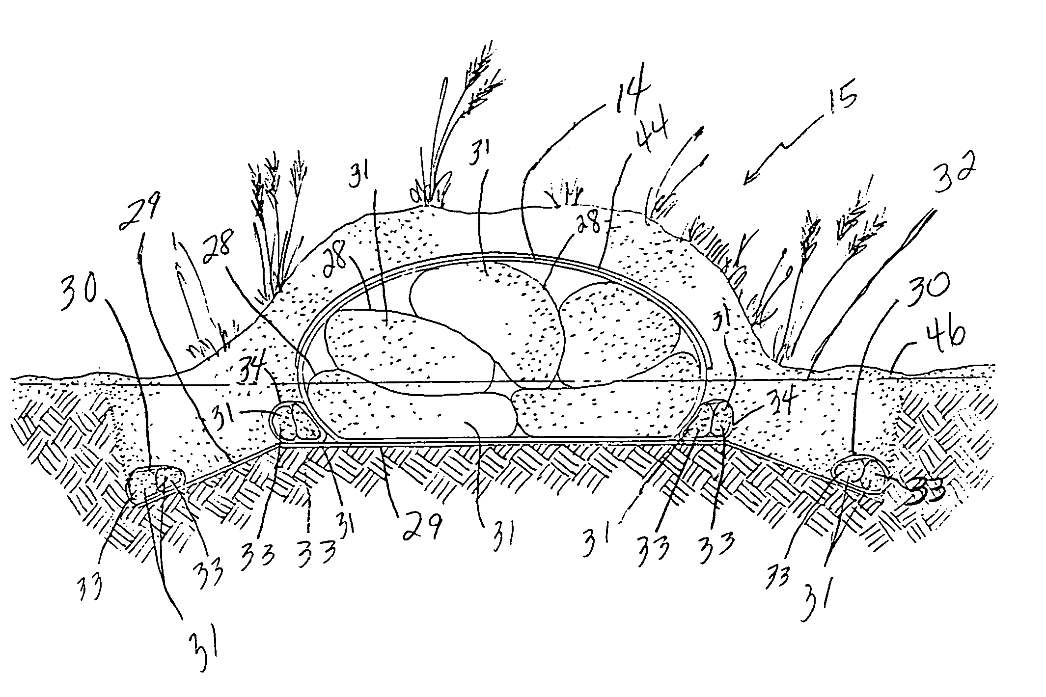
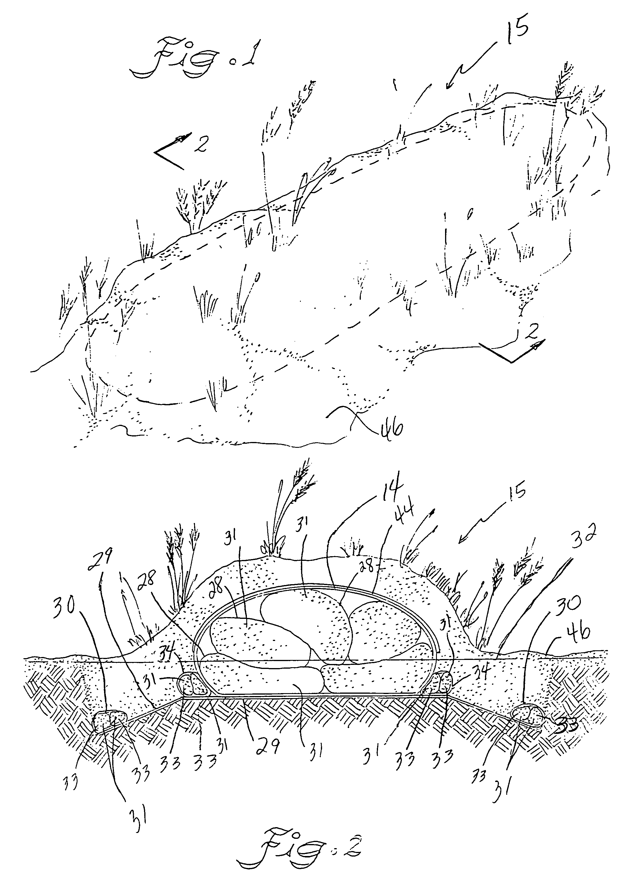
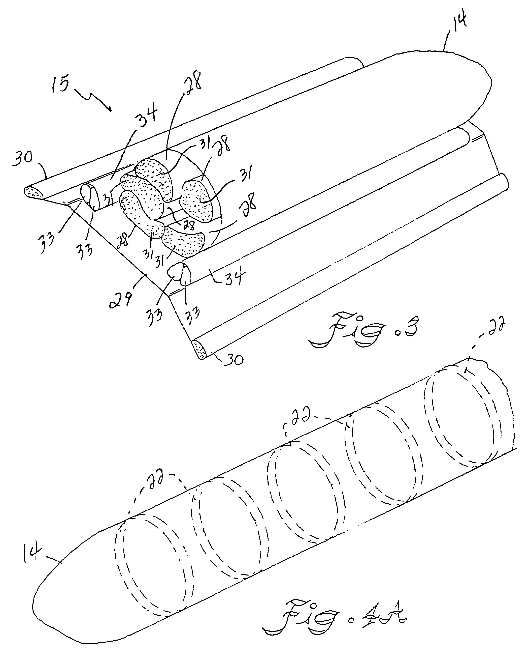
[0051]A presently preferred embodiment of the apparatus and method of deploying a geotextile container 14 is schematically show...


PUM


Abstract

A geotextile container and system for constructing a water barrier or dam is disclosed. A system for maintaining fill material solids in position to form a barrier comprises an elongated sheet of geotextile material capable of coiling upon itself to form a helical structure. Further, a means for seaming the first elongated sheet into a tubular container and filling the container with solids is presented. Fill material solids may be held in position by a tubular shaped container that forms a barrier or dam. An inner liner also may be employed in the tubular container. Cradle tubes may be deployed on either side to hold the container in position, such as when the container is struck by high energy waves.

Description

CROSS REFERENCE TO RELATED APPLICATIONS[0001]Priority is hereby claimed on application U.S. Ser. No. 60 / 147,316 which is a provisional application entitled: APPARATUS AND METHOD FOR DEPLOYING GEOTEXTILE TUBES” filed Aug. 5, 1999.BACKGROUND OF THE INVENTION[0002]The present invention relates to the art of geotextile containers of the type for maintaining fill material and more particularly to a method and apparatus for deploying same.[0003]Conventional geotextile tubes, whether woven on a circular loom or formed by joining two or more mill widths of fabric, have a tendency of rolling forward, as well as backward during the process of filling the tube with solid material. This rolling also tends to occur when the filled tube is hit with forceful wave action.[0004]In a typical application an elongated prior art geotextile container may be constructed with a water permeable geotextile fabric. This geotextile fabric can be defined by its Apparent Opening Size (A.O.S.) as it relates to a ...

Claims


Application Information

Patent Timeline
Patent Type & Authority Patents(United States)
IPC IPC(8): E02B3/04E02B3/12E02B3/10
CPCE02B3/108E02B3/127Y02A10/11
Inventor BRADLEY, ANTHONY S.
Owner BRADLEY INDAL TEXTILES
Why Eureka
Try Eureka