Method for testing the serviceability of transducers

a technology of two-wire transducers and serviceability, which is applied in the direction of motor/generator/converter stoppers, dynamo-electric converter control, instruments, etc., can solve problems such as errors

Inactive Publication Date: 2008-04-15
ABB PATENT GMBH
View PDF4 Cites 7 Cited by
  • Summary
  • Abstract
  • Description
  • Claims
  • Application Information

AI Technical Summary

Benefits of technology

[0012]This test is advantageously performed when the transducer is put into service or whenever the transducer supply voltage is switched on. The loss of serviceability because of insufficient operating voltage during the subsequent intended use of the transducer is thereby advantageously avoided.
[0015]According to a further feature of the invention, the loop current is increased continuously from the minimum value to the maximum value. This advantageously makes it possible to increase the loop current from the minimum value to the maximum value in a technically simple manner.
[0020]By using a DC-compensated AC signal for transmitting the signal, any effect of the DC loop current on the two-wire line and hence on the input voltage across the internal resistance of the transducer is advantageously avoided. The detected error is thereby immediately indicated to the remote operating staff, in particular for transducer testing performed as required or periodically. Consequently, the fact that the transducer concerned is not serviceable is detected immediately, thereby avoiding the intended use of a transducer that is not serviceable.

Problems solved by technology

If the input voltage falls below a definable threshold value that is greater than the minimum input voltage required to maintain serviceability, before the loop current has reached its maximum value, this situation is judged to be an error.
If an error is detected, the DC loop current is reduced until the input voltage reaches at least the definable threshold value, thereby signaling an error.

Method used


Image

  • Method for testing the serviceability of transducers
  • Method for testing the serviceability of transducers
  • Method for testing the serviceability of transducers

Examples


Embodiment Construction

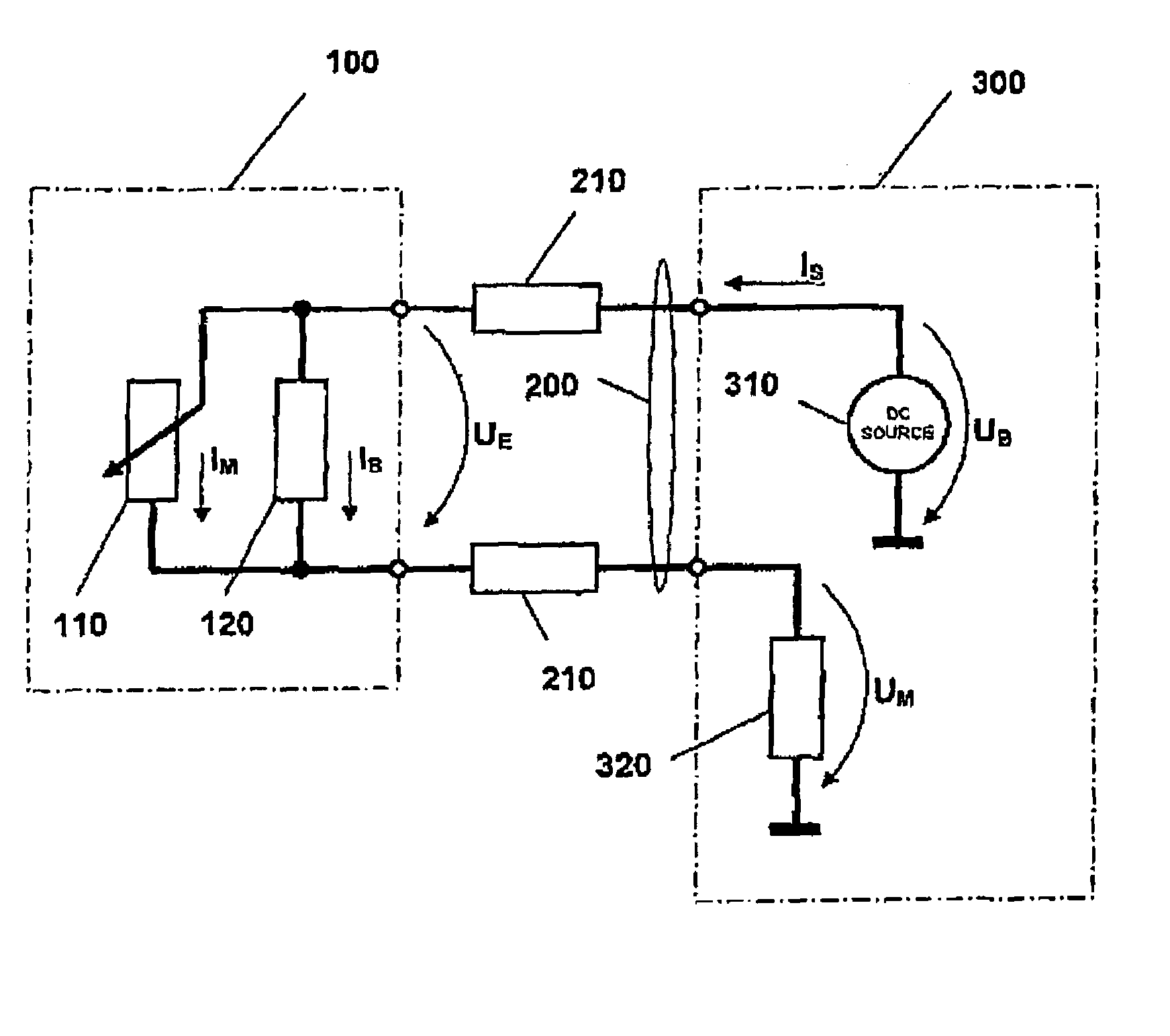
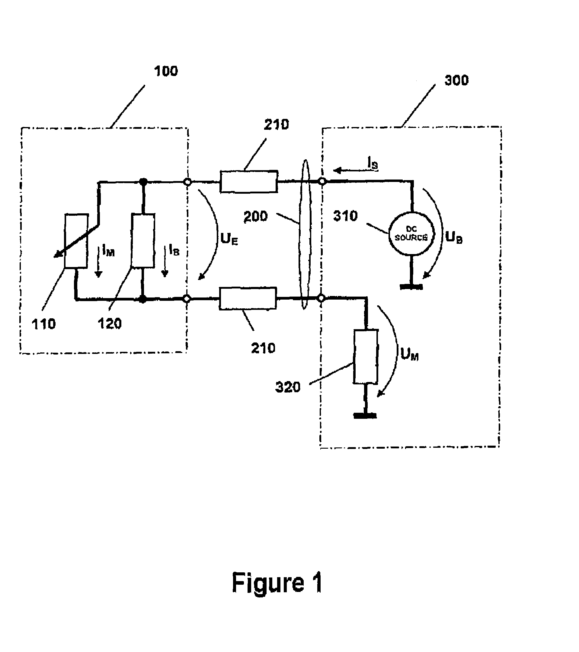
[0025]A transducer 100 is connected via a two-wire line 200 to a transducer power supply unit 300 located in the control area. The transducer power supply unit 300 comprises at least one DC voltage source 310 having an operating voltage UB and a measuring resistor 320. A conductor loop is taken as a mesh from the DC voltage source 310 via the two-wire line 200, transducer 100 and the measuring resistor 320.

[0026]The two-wire line 200 has for each wire a line resistance 210 that depends on the cross-section and length of the line.

[0027]The transducer 100 has an internal resistance formed by the parallel connection of a fixed internal resistance 120 and a variable internal resistance 110. The fixed internal resistance 120 here represents the loading of the conductor-loop circuit by the active components of the transducer 100 given by the operating current IB. The operating current IB is kept constant during the intended use of the transducer 100.

[0028]The transducer 100 is equipped wi...


PUM


Abstract

The invention relates to a two-wire transducer in automation engineering that outputs a measurement signal as an injected current. For the method to test the serviceability, it is proposed to increase the DC loop current (IS), independently of the measured value, from the minimum value towards the maximum value (ISM), and to measure the input voltage (UE) across the internal resistance of the transducer in the process, and to compare it with a definable threshold value (UES) that is greater than the minimum input voltage (UEM) required to maintain serviceability. If the input voltage (UE) falls below the threshold value (UES) before the DC loop current (IS) has reached its maximum value (ISM), the DC loop current (IS) is reduced until the input voltage (UE) reaches at least the definable threshold value (UES), and the error is signaled.

Description

CROSS REFERENCE TO RELATED APPLICATION[0001]This application claims priority from German Application DE 10 2005 047 894.8 filed on Oct. 6, 2005 the contents of which are relied upon and incorporated herein by reference in their entirety, and the benefit of priority under 35 U.S.C. 119 is hereby claimed.BACKGROUND OF THE INVENTION[0002]The invention relates to a method for testing the serviceability of two-wire transducers in automation engineering that output a measurement signal as an injected current.[0003]The transducer in this case is located remotely in the field environment, local to the process, and is equipped with sensor means for detecting a physical process variable and means for converting it into an electrical variable.[0004]For a multiplicity of transducers, means are kept in a central control area for supplying them with power and for measured-value processing and visualization in the control area.[0005]In a two-wire transducer, both the supply of electrical power to ...

Claims


Application Information

Patent Timeline
Patent Type & Authority Patents(United States)
IPC IPC(8): G01R31/08
CPCG01R31/2829
Inventor SCHOLZ, WOLFANG
Owner ABB PATENT GMBH
Why Eureka
Try Eureka