
Method and system for digital rendering over a network

a network and network technology, applied in the field of digital rendering systems, can solve the problems of increasing the size of the file or array containing the model, increasing the model, and not being suitable for viewing, so as to achieve the effect of conserving the bandwidth between the client site and the rendering service si

Inactive Publication Date: 2010-03-30
DATACLOUD TECH LLC
View PDF4 Cites 9 Cited by
  • Summary
  • Abstract
  • Description
  • Claims
  • Application Information

AI Technical Summary

Benefits of technology

This approach conserves bandwidth, reduces redundant tasks, and enhances rendering efficiency by transmitting only necessary data, enabling faster rendering and improved workflow management in distributed animation environments.

Problems solved by technology

The size of the file or array containing the model will increase, of course, as the complexity of the model increases.
At this point, the virtual objects are still expressed in three-dimensional form and are not suitable for viewing, except perhaps in “wireframe” renditions as the animation is perfected.
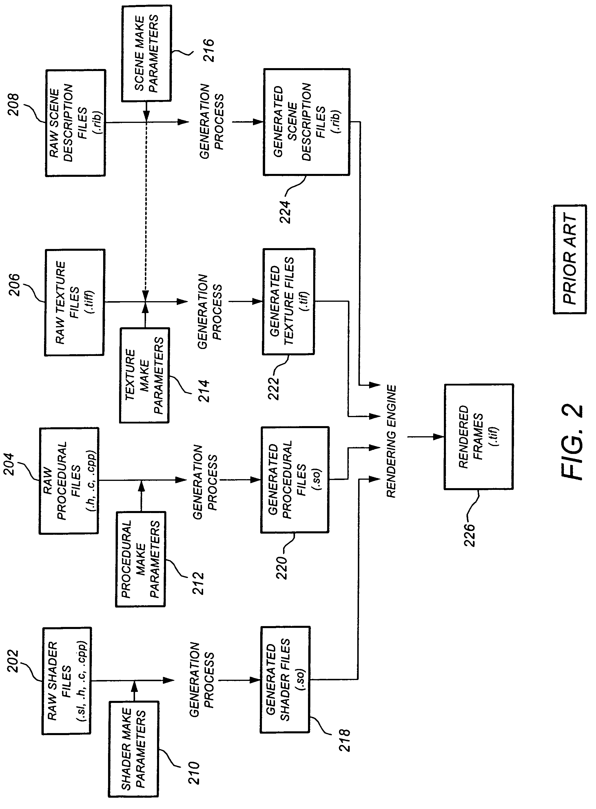
Although they are automatically created by the modeler, these raw or “uncompiled” files are usually in ASCII format or other human-readable format and are not directly usable by the rendering engine.
A problem arises in conventional 3-D computer animation studios today as a result of the massive computational power needed by the rendering engines.
According to an exemplary prior art system, generation of rendering resources is not coordinated in a systematic manner, and often the rendering engine and other network resources end up performing redundant generation and / or rendering tasks.
The conventional scenario may be particularly frustrating for a user who has only made a minor tweak or addition to their model or another rendering resource.
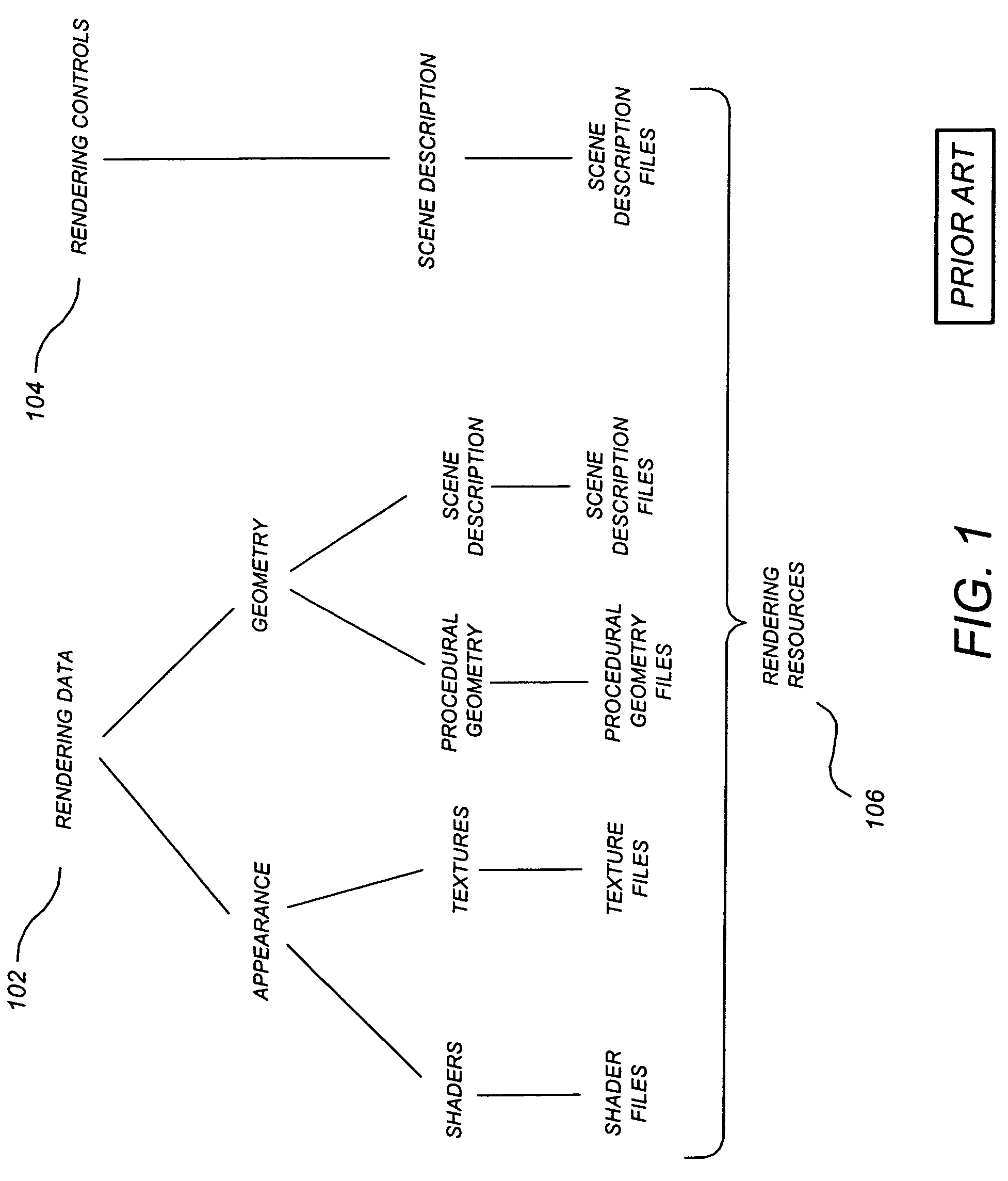
While shader files and procedurals may generally be “slim” resources not requiring excessive bandwidth, scene description files and textures can be massive in size.
Accordingly, it could be quite frustrating for a remote user who has made a minor tweak in their rendering resources to require resubmission of these massive amounts of rendering resource data to the online rendering engine.

Method used


Image

  • Method and system for digital rendering over a network
  • Method and system for digital rendering over a network
  • Method and system for digital rendering over a network

Examples


Embodiment Construction

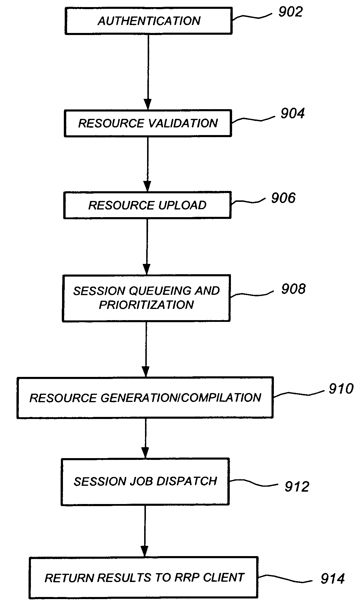
[0044]The preferred embodiments described herein may be advantageously used in conjunction with the system described in Nicolas et. al., “Method and System for Creating and Managing a Digital Content Creation Project Over a Network,” U.S. Ser. No. 09 / 738,466, filed Dec. 15, 2000, (BEL-020), which is assigned to the assignee of the present invention, and which is incorporated by reference herein. A remote rendering protocol (rrp) refers to methods and protocol items used to provide an efficient, reduced-redundancy rendering service for rendering data produced at a client site, as described herein. A goal of the rrp is to establish a fundamental interface for the rendering service. The rrp provides user authentication, session control, render description, status control and monitoring, and resultant image transfer dialog items.

[0045]The challenge of a qualitative remote rendering service is on both the imagery produced and the ability to sustain a balance between rendering compute tim...


PUM


Abstract

A method, system, computer program product, and protocol for digital rendering over a network is described. Rendering resources associated with a project are stored in a project resource pool at a rendering service site, and for each rendering request received from a client site the project resource pool is compared to current rendering resources at the client site. A given rendering resource is uploaded from the client site to the rendering service only if the project resource pool does not contain the current version, thereby conserving bandwidth. In accordance with a preferred embodiment, redundant generation of raw rendering resource files is avoided by only generating those raw rendering resource files not mated with generated rendering resource files. Methods for reducing redundant generation of raw resources are also described, as well as methods for statistically reducing the number of raw resource files required to be uploaded to the rendering service for multi-frame sessions. The preferred embodiments are particularly advantageous for remote rendering services at a different site from the client and connected across the Internet or a Wide Area Network, but may also be applied where the rendering service is co-located with the client site and connected thereto by a Local Area Network (LAN).

Description

CROSS-REFERENCE TO RELATED APPLICATIONS[0001]This application is a continuation of U.S. application Ser. No. 09 / 925,157, which was filed on Aug. 8, 2001, and which issued as U.S. Pat. No. 7,266,616 on Sep. 4, 2007.FIELD OF THE INVENTION[0002]This patent specification relates to digital rendering systems. In particular, it relates to a method and system for efficient digital rendering over a network.BACKGROUND OF THE INVENTION[0003]Three-dimensional computer animation continues to intensely impact the visual arts world. In the entertainment industry, for example, three-dimensional computer animation has provided the sole basis for several motion pictures, and computer-generated visual effects are increasingly used to enhance or replace filmed scenery, special effects, and stunts in filmed motion pictures. Additionally, three-dimensional computer animation has furthered the sciences and practical arts by allowing, for example, visual analysis of product designs prior to physical assem...

Claims


Application Information

Patent Timeline
Patent Type & Authority Patents(United States)
IPC IPC(8): G06F15/16
CPCG06T15/00G06T2200/16G06T2210/08H04L67/42H04L69/16H04L67/025H04L67/14H04L67/01
Inventor MUNSHI, AAFTAB A.BLEIWEISS, AVI I.
Owner DATACLOUD TECH LLC
Learn More