Apparatus and method for equalizing received signals

a technology of equalizer circuit and received signal, which is applied in the direction of pulse technique, pulse manipulation, baseband system details, etc., can solve the problems of signal distortion, distortion generally occurring, and signal distortion often manifesting, and achieve acceptable linearity, advantageous use, and high speed

Active Publication Date: 2005-07-12
TEXAS INSTR INC
View PDF4 Cites 7 Cited by
  • Summary
  • Abstract
  • Description
  • Claims
  • Application Information

AI Technical Summary

Benefits of technology

[0012]It is, therefore, an object of the present invention to provide an apparatus and method for equalizing input signals including high and low frequency signal components that may be advantageously employed in high speed, low voltage operations, with acceptable linearity.
[0013]It is a further object of the present invention to provide an apparatus and method for equalizing input signals including high and low frequency signal components that may be advantageously employed in high speed, low voltage operations and has ample voltage headroom to permit flexibility in operation and accommodate voltage swings in the input signals, with acceptable linearity.

Problems solved by technology

Transmission of a communication signal over a cable typically causes distortion of the signal.
This distortion generally occurs as frequency dependent attenuation and variations in the signal which are affected by cable length, temperature, interconnection losses and other factors.
The signal distortion is often manifested in inter-symbol interference.
There has been less success in providing an equalizer apparatus for operating at high speeds (for example, 1 gigabit per second or faster) in low voltage systems (for example, less than 3 volts).
Operation of Baker's apparatus at higher speeds (for example, approximately 1 gigabit per second) would not provide acceptable performance.
Higher currents cause greater power dissipation that is manifested principally as increased heat.
Thus, greater heat contributes to lowered reliability or to greater cost, and may contribute to both lower reliability and greater cost.
This increased voltage drop in Shakiba's apparatus limits voltage headroom and adversely limits voltage swings that can be accommodated by his apparatus.
Feedback is known to create limitations with respect to stability.
Some circuits become very nonlinear when large input signals are applied to them.
Feedback, as mentioned earlier herein, is not conducive to high speed operations.

Method used


Image

  • Apparatus and method for equalizing received signals
  • Apparatus and method for equalizing received signals
  • Apparatus and method for equalizing received signals

Examples


Embodiment Construction

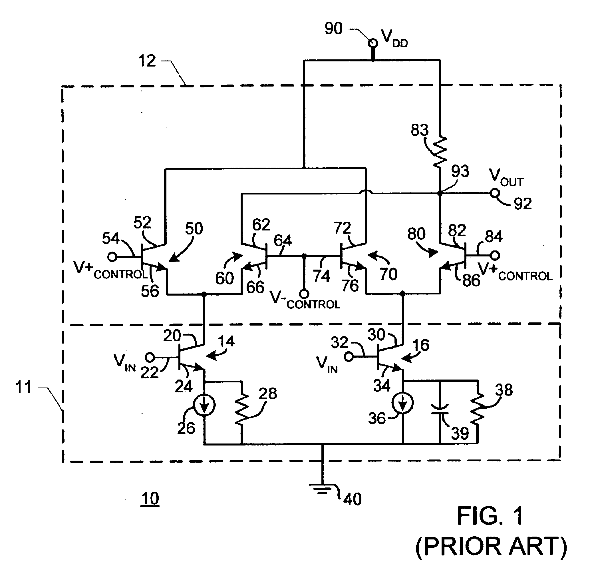
[0019]FIG. 1 is a simplified electronic schematic diagram of an exemplary prior art equalizer apparatus. In FIG. 1, an equalizer apparatus 10 includes a constant transconductance gain section 11 and a variable gain section 12. Variable gain section 12 employs differential control signals V+CONTROL, V−CONTROL to control gain variance. Constant transconductance gain section 11 includes transistors 14, 16, current sources 26, 36, resistors 28, 38 and capacitor 39. Variable gain section 12 includes transistors 50, 60, 70, 80 and resistor 83. Transistor 14 has a collector 20, a base 22 and an emitter 24. Collector 20 is coupled with voltage-bias section 12. Emitter 24 is coupled with ground 40 via a current source 26 in parallel with a resistor 28. Transistor 16 has a collector 30, a base 32 and an emitter 34. Collector 30 is coupled with voltage-bias section 12. Emitter 34 is coupled with ground 40 via a current source 36 in parallel with a resistor 38 and a capacitor 39. An input signa...


PUM


Abstract

An apparatus for equalizing input signals including high and low frequency component signals received at an locus includes: (a) a first signal amplifying circuit coupled with the input locus, blocking the low frequency component signals and amplifying the high frequency component signals by a first gain to present a first amplified signal; the first gain is established by a relationship between at least two resistance elements in the first signal amplifying circuit; (b) a second signal amplifying circuit coupled with the input locus amplifying the input signal by a second gain to present a second amplified signal; and (c) a combining circuit combining the first amplified signal and the second amplified signal to present an output signal representative of the input signal at an output locus.

Description

BACKGROUND OF THE INVENTION[0001]The present invention is directed to equalizer circuits, and especially to adaptive equalizer circuits for use in equalizing received signals that have been conveyed over a length of a transmission medium, such as a communication cable. The present invention may be advantageously employed for equalizing a received signal that includes high frequency and low frequency component signals. The present invention is especially useful in equalizing communication signals received over a cable or similar signal conveyance. The exemplary embodiment of the present invention disclosed herein is an equalization apparatus in a receiver in a data communication system that receives signals from a communication cable. The equalization apparatus of the present invention employs signal equalization to compensate for the low pass characteristics of a communication cable. The scope of structure, application and employment of the present invention is not intended to be li...

Claims


Application Information

Patent Timeline
Patent Type & Authority Patents(United States)
IPC IPC(8): H04B3/04H04B3/14
CPCH04B3/143
Inventor GONDI, SRIKANTH
Owner TEXAS INSTR INC
Why Eureka
Try Eureka