Dual polarization antenna and associated methods

a dual-polarization antenna and associated technology, applied in the field of communication, can solve the problems of element-to-module interconnection, and may not meet stringent requirements for efficiency over octave plus or greater bandwidth

Inactive Publication Date: 2008-04-15
NORTH SOUTH HLDG
View PDF17 Cites 245 Cited by
  • Summary
  • Abstract
  • Description
  • Claims
  • Application Information

AI Technical Summary

Problems solved by technology

However, when wide bandwidth and high electronic scan angles are desired, these antennas may not meet stringent requirements on efficiency over octave plus or greater bandwidths.
Since coupling changes substantially over wide bandwidths, maintaining efficiency at all desired scan angles may not be possible.
Therefore another possible drawback in some of these systems is the element-to-module interconnect, such as the feed network described in U.S. Pat. No. 6,483,464, that is essentially hand-made without using automated manufacturing techniques.
Any handmade feed network would require many man-hours to build the thousands required for a large antenna array, thus the cost would typically be prohibitive.
These array elements are suited for automated manufacturing, but not for operating bandwidths much in excess of 30%.
Some Visalia antenna arrays have bandwidths in excess of an octave, but suffer depth and integration issues for low profile electrically scanned antenna (ESA) applications.
A noncontiguous ground plane is used in some of these antennas, making this type of antenna array difficult to adapt to automated manufacturing.
Other dipole array antennas have acceptable bandwidth, but employ feed networks that are not suited for low cost automated manufacturing or applicable to pick-and-place and associated surface mount technology.

Method used


Image

  • Dual polarization antenna and associated methods
  • Dual polarization antenna and associated methods
  • Dual polarization antenna and associated methods

Examples


Embodiment Construction

[0023]The present invention will now be described more fully hereinafter with reference to the accompanying drawings, in which preferred embodiments of the invention are shown. This invention may, however, be embodied in many different forms and should not be construed as limited to the embodiments set forth herein. Rather, these embodiments are provided so that this disclosure will be thorough and complete, and will fully convey the scope of the invention to those skilled in the art. Like numbers refer to like elements throughout, and prime notation is used to indicate similar elements in alternative embodiments.

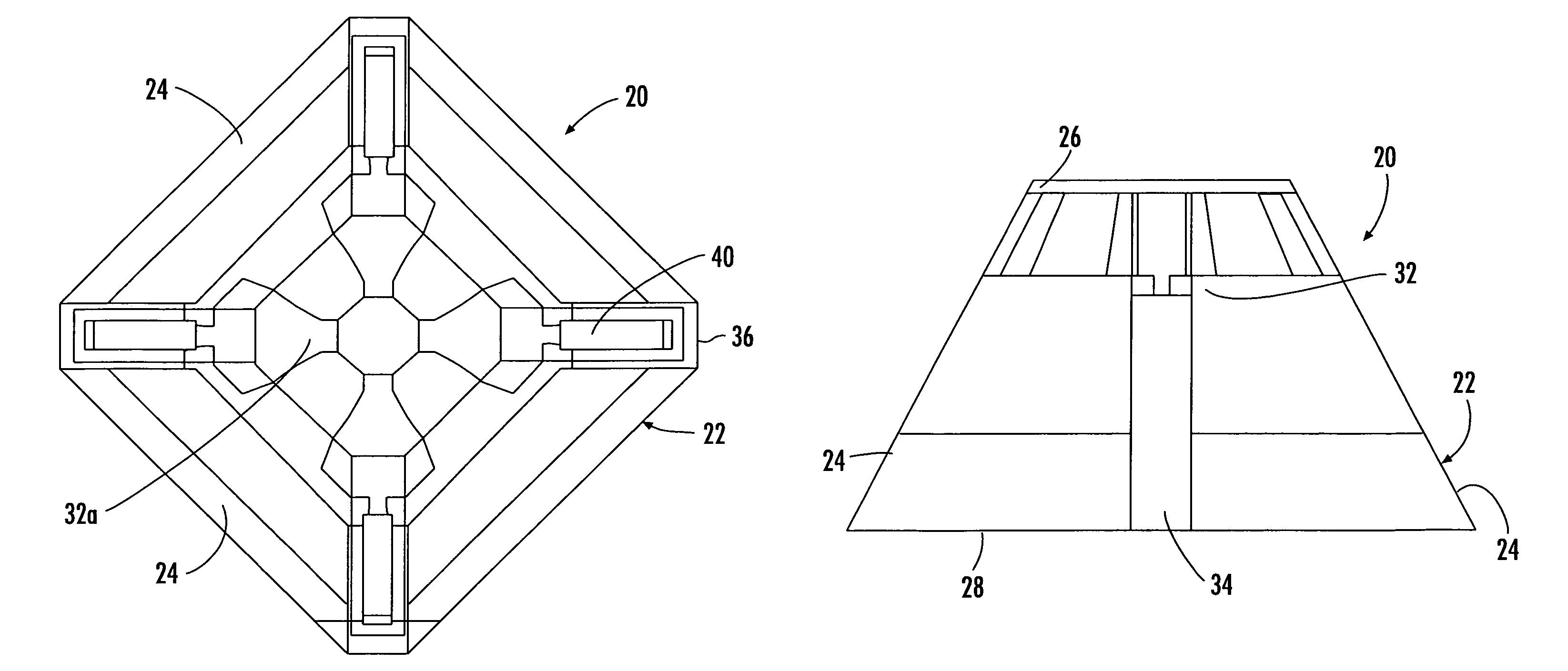
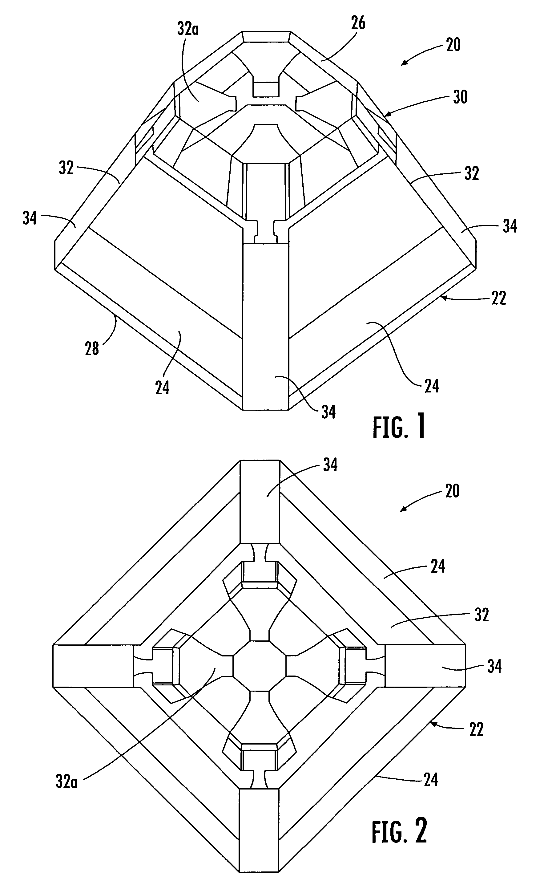
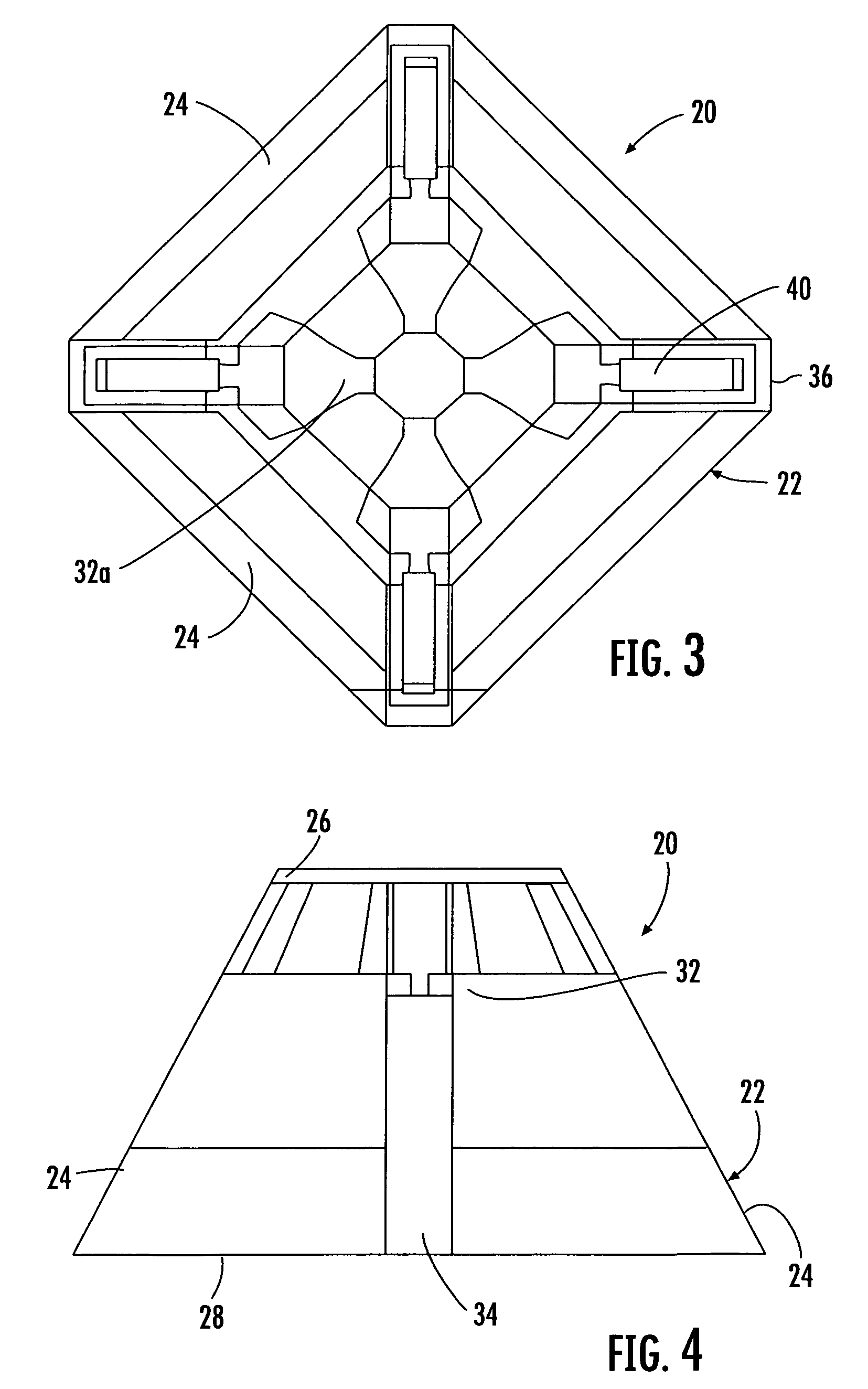
[0024]The dual polarization antenna element of the present invention is formed as a molded element, for example, a Molded Interconnect Device (MID), and replaces the typical feed network and aperture commonly used with dipole array antennas. The antenna element can be formed to adhere to basic antenna principals set forth in the article entitled, “Wide-Slotted Printed Slotl...


PUM


Abstract

A dual polarization antenna includes a substantially pyramidal configured substrate having opposing walls. An antenna element is carried at each wall such that opposing pairs of antenna elements define respective antenna dipoles and provide dual polarization.

Description

FIELD OF THE INVENTION[0001]The present invention relates to the field of communications, and more particularly, to a dual polarization antenna element used in phased array antennas.BACKGROUND OF THE INVENTION[0002]Existing microwave antennas include a wide variety of configurations for various applications, such as satellite reception, remote broadcasting, or military communication. The desirable characteristics of low cost, lightweight, low profile form factors and mass producibility are provided in general by printed circuit antennas, wherein flat conductive elements are spaced from a single essentially continuous ground element by a dielectric sheet of uniform thickness. The antenna elements are designed in a periodic or a periodic array of like elements and may be used for communication systems such as Identification of Friend / Foe (IFF) systems, Personal Communications Service (PCS) systems, satellite communications systems, and aerospace systems, which require such characteris...

Claims


Application Information

Patent Timeline
Patent Type & Authority Patents(United States)
IPC IPC(8): H01Q1/36
CPCH01Q9/28H01Q9/30H01Q21/24H01Q21/26
Inventor SNYDER, CHRISGOTHARD, GRIFFIN K.KRALOVEC, JAY
Owner NORTH SOUTH HLDG
Why Eureka
Try Eureka